Introduction
Most injection molding teams obsess over the obvious parameters—melt temperature, injection pressure, clamp force—while five lesser-known settings directly determine whether a part ships or gets scrapped. Even when your process sheet shows identical setpoints run after run, two identical machines can produce a 40°F difference in actual melt temperature, causing one press to run at 3% scrap and the other to exceed 10%.
That gap between what you program and what the plastic actually experiences creates shot-to-shot inconsistency, cosmetic defects, and dimensional variation that cost OEMs significant time and material waste. The fix isn't new equipment: it's revisiting the settings most teams lock in during trials and never touch again.
Key Takeaways
- Machine setpoints tell you what you asked for; process outputs tell you what actually happened
- Five overlooked settings drive more quality improvement than standard adjustments: melt cushion, V/P transfer point, back pressure, multi-stage hold, and cooling time
- Each setting targets a specific defect — from flash and short shots to sink marks and ejection failure
- Small, deliberate changes to these parameters reduce scrap without retooling
- Knowing why each setting matters is just as critical as knowing how to change it
Why Machine Setpoints Don't Tell the Whole Story
Machine setpoints represent your instructions to the press, not the plastic's actual experience. Hydraulic wear, screw design differences, and thermocouple placement mean the same setpoint can produce wildly different results. One documented case revealed identical process setpoints on two identical presses yielded a 40°F melt temperature gap: one machine ran at 3% scrap, the other exceeded 10%. Only after measuring actual melt temperature with a pyrometer and adjusting for the real output did scrap rates equalize.
Most defect troubleshooting chases the usual suspects: barrel temperature, injection pressure, and cycle time. Meanwhile, the five settings below go unexamined. This leaves repeatable quality gains on the table because teams validate processes by matching numbers on a setup sheet rather than monitoring what the plastic actually does inside the mold.
Output-based monitoring addresses this directly. Instead of trusting hydraulic pressure readings (which vary wildly between machines due to intensification ratios), cavity pressure sensors placed inside the mold measure post-gate and end-of-fill pressures directly. Tracking fill time, gate seal timing, and actual cushion values gives a reliable picture of process health that setpoint records alone can't provide. That shift from machine-centric to plastic-centric monitoring is exactly what makes the five settings below worth examining.

5 Underrated Injection Molding Machine Settings That Improve Part Quality
Melt Cushion
Melt cushion is the small volume of molten material remaining in front of the screw at the end of the hold phase. This "leftover" plastic acts as a pressure buffer, and a consistent cushion value—typically 0.10 to 0.25 inches (2.5 to 6.4 mm)—signals shot-to-shot material consistency. Without adequate cushion, the screw bottoms out, dropping cavity pressure to zero and making it impossible to compensate for viscosity shifts.
Why it's underrated: Most operators set shot size and screw recovery targets during trials but never establish alarm limits around final cushion. In one case, a molder transferred a validated process to a recently serviced machine and immediately experienced dimensional failures. The root cause? The replacement screw was six inches shorter than specified, turning an assumed 0.250-inch cushion into a massive 6.250-inch cushion. This oversized cushion acted like a sponge, absorbing pack pressure and preventing adequate material from reaching the cavity.
Quality impact: Inconsistent or near-zero cushion directly causes short shots, underpacked parts, and dimensional variation across cavities. Because molten plastic is compressible, an excessively large cushion absorbs applied pack pressure instead of transmitting it into the mold. Best practice is to maintain cushion around 0.20 inches (5 mm) for screw diameters of 25–60 mm, with tight alarm limits of ±0.05 inches (2 mm) to detect screw wear or check-ring leakage before defects appear.
V/P Transfer Point (Velocity-to-Pressure Switchover)
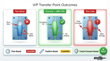
The V/P transfer point marks the moment the machine switches from velocity-controlled injection to pressure-controlled packing. Most operators set this by time or percentage of stroke, but it should be set by screw position—or ideally, cavity pressure—for true repeatability. The transfer should occur when the mold is approximately 95% full; too early causes short shots and sink marks, too late causes flash and mold damage.
Why it's underrated: Time-based transfer is common because it's simple to enter, but it fails to adapt when material viscosity shifts due to lot changes or temperature drift. If viscosity drops, a time-based transfer over-packs the mold and causes flash; if viscosity increases, the result is a short shot. Position-based transfer locks fill volume regardless of these variables, ensuring consistent filling shot after shot.
Quality impact: An improperly set transfer point is a leading cause of flash, short shots, and part-to-part weight variation. Cavity-pressure-based transfer (Decoupled III) provides the highest process capability by automatically adjusting machine energy to maintain target in-cavity pressure, absorbing viscosity shifts without defect generation. Switching from time-based to position-based transfer is a low-effort change that directly stabilizes fill volume and cuts flash-related scrap.
Back Pressure During Screw Recovery
Back pressure is the resistance applied against the retracting screw during plasticizing. It controls how densely and uniformly the melt is packed before the next shot, directly affecting melt homogeneity, dissolved gas elimination, and colorant or additive distribution.
Material suppliers generally recommend back pressure between 500 and 1,000 specific psi (plastic pressure, not hydraulic) for materials like polypropylene and ABS.
Where it goes wrong: Back pressure is often left at factory default or set very low to reduce cycle time, without considering the material's specific requirements for a homogeneous melt. The tradeoff between cycle time and melt quality is rarely documented. Worse, operators sometimes adjust back pressure as a quick fix for unrelated defects, masking root causes and altering melt density unpredictably.
Quality impact: Too-low back pressure allows air and volatiles to remain in the melt, causing voids, splay, and inconsistent color distribution. Too-high back pressure introduces excessive shear heating that degrades polymers (especially shear-sensitive materials like PVC or acetal) and extends screw recovery time unnecessarily. The correct value should be validated by visual part inspection and melt temperature checks, not set arbitrarily or used as a band-aid for unrelated issues.
Multi-Stage Hold Pressure Profile
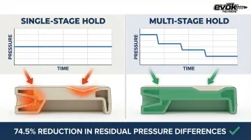
Multi-stage hold pressure uses two or more decreasing pressure steps during the packing and holding phase rather than a single flat hold pressure value. Plastic shrinks as it cools, and a stepped profile compensates for progressive shrinkage as the gate area solidifies. A study on complex, thick-walled components showed that a multi-stage profile reduced residual pressure differences by 74.5% (from 48.7 MPa to 12.5 MPa) and width deviation by 66.7% compared to single-stage flat hold.
Why it's underrated: Single-stage hold is the default on most machines and the default in most setup sheets. Engineers rarely revisit it because parts "look okay," but dimensional measurements and long-term warp issues reveal the gap. A single high-pressure flat hold often over-packs the gate area—inducing severe residual stress—while failing to push enough material to the extremities before the gate freezes.
The real cost: Sink marks occur in thicker sections when the outer skin solidifies while the inner core is still shrinking, pulling material inward. A properly profiled multi-stage hold reduces sink marks, internal residual stress, and warpage—especially in thick-walled sections or parts with significant geometry variation. By starting high to pack extremities and stepping down as the gate solidifies, molders eliminate sink marks without flashing the mold.
Scientifically Determined Cooling Time
Most molders set cooling time by adding an arbitrary safety buffer to whatever time seemed to work during trials, rather than running a gate seal test or targeting a specific ejection temperature for the material. Cooling time often accounts for up to 80% of the total injection molding cycle, making it a critical lever for both quality and efficiency.
Why it's underrated: Cooling time is treated as a quality knob only when parts stick or warp at ejection. The opportunity to reduce it methodically—via gate seal confirmation and thermal analysis—is missed, leaving both cycle time and part quality optimization on the table.
How to set it correctly: Insufficient cooling produces warp, sink, and ejector pin marks; excessive cooling wastes cycle time and money. A scientific gate seal study is the right starting point:
- Run the optimized process with zero hold time and weigh the parts
- Incrementally add hold time in 0.5 to 1.0-second steps, weighing parts after each increment
- Stop when part weight plateaus (a change of at least 0.1g is considered significant) — that plateau marks gate freeze
- Add a 1 to 2-second buffer beyond gate freeze time to account for process variation
From there, pull the material data sheet and find the Heat Deflection Temperature (HDT), the point at which the part will deflect under load. Calculate the time required for the part to reach HDT in the mold, then add a 20% safety buffer. That final number is your scientifically grounded cooling time.
How to Monitor and Apply These Settings in Practice
Documenting output values—actual cushion, actual fill time, actual gate seal time—alongside setpoints on a process record sheet is the first step to catching drift before it becomes a defect. This approach aligns with scientific molding best practices and doesn't require advanced sensor technology to start. A simple spreadsheet tracking these outputs per shift or per production run creates visibility into process health that setpoint records alone can't provide.
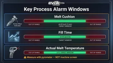
Establishing alarm windows around each of the five settings creates an early warning system that reduces reliance on end-of-line inspection:
- Melt cushion: ±0.05 inches (2 mm) to detect screw wear or check-ring leakage
- Fill time: ±0.04 seconds to catch viscosity shifts or machine wear
- Actual melt temperature: ±3°C (±5.4°F) measured with a pyrometer, not the machine screen
That kind of structured monitoring is also what separates reactive troubleshooting from proactive quality control. Evok Polymers embeds this discipline—process record sheets, alarm windows, and scientific molding protocols—directly into part development and manufacturing partnerships, so OEM clients see consistent results from the first production run rather than discovering problems mid-campaign.
Tackle one setting per production run review rather than adjusting all five at once. Isolating variables is how you understand what's actually driving improvement. A basic DOE approach prevents chasing multiple changes simultaneously.
Taguchi-based DOE consistently identifies which parameters control part quality; one study found cooling time drove 28.78% of warpage variance in PET preforms, followed by cycle time (21.65%) and melt temperature (18.06%). Knowing which levers matter most means you stop guessing and start adjusting with purpose.
Conclusion
The difference between acceptable and exceptional injection molded parts often lives in the settings most teams set once and forget. Small, deliberate attention to melt cushion, V/P transfer point, back pressure, hold pressure profiling, and cooling time can meaningfully reduce defect rates and improve dimensional consistency without new tooling investment.
These five settings aren't exotic—they're already on your machine. The opportunity is treating them as active quality levers rather than static values copied from a setup sheet.
If you want these optimizations built into your part development process from the start—rather than discovered through scrap—EVOK Polymers brings 25+ years of injection molding experience, Six Sigma black belt process engineering, and a track record with OEMs across medical, powersports, and packaging to help you get there.
Frequently Asked Questions
What are the 4 steps of injection molding?
The injection molding cycle consists of four primary phases: clamping (the mold closes under pressure), injection (molten plastic is injected into the mold cavity), cooling (the plastic solidifies to the shape of the cavity), and ejection (the mold opens and the finished part is ejected).
What causes short shots in injection molding?
Short shots occur when the mold cavity doesn't fill completely. Common causes include insufficient injection pressure, a V/P transfer point set too early (before the mold is 95% full), low melt temperature, or an inadequate melt cushion that lets the screw bottom out before the part is packed.
How does back pressure affect part quality in injection molding?
Back pressure controls melt consistency during screw recovery by compressing the plastic and expelling air and volatiles. Too little leads to voids, splay, and uneven colorant distribution; too much can degrade shear-sensitive materials and add seconds to every cycle.
What is the V/P transfer point and why does it matter?
V/P transfer is the switchover from velocity-controlled filling to pressure-controlled packing. Setting it by screw position rather than time prevents overfill (flash) or underfill (short shots) caused by viscosity changes and machine variation. This keeps volumetric filling consistent regardless of material lot shifts.
How do sink marks form and how can hold pressure settings reduce them?
Sink marks form when the outer skin solidifies while the inner core is still shrinking, pulling the surface inward. A multi-stage hold pressure profile forces additional material into the cavity before the gate freezes, packing out the depression without over-stressing the gate.
How do you determine the correct cooling time for an injection molded part?
Use a gate seal test—incrementally adding hold time until part weight plateaus—to confirm the gate is frozen, then cross-reference the material's Heat Deflection Temperature (HDT) from the data sheet. Calculate the time needed to reach HDT and add a 20% safety buffer instead of relying on an arbitrary setting.