The good news: specific, actionable design changes can measurably improve part durability without requiring expensive tooling overhauls. This guide covers wall thickness optimization, ribbing strategy, radii application, draft angles, gate placement, and material selection—all decisions that determine how your part handles stress, load, and environmental exposure over its service life.
Key Takeaways
- Keep wall thickness variations within ±15% for semi-crystalline resins to prevent warping and stress concentration
- Corner radii should be at least 0.5x nominal wall thickness to eliminate stress-riser points where cracks initiate
- Rib thickness at 40-60% of nominal wall adds stiffness without creating sink marks on the show surface
- For textured surfaces, add 1.5° of draft per 0.001" of texture depth to reduce ejection stress
- Material selection is a design-stage decision: switching resins after tooling means expensive mold modifications
Why Part Durability Starts at the Design Stage
The majority of injection molded part failures are traceable to design decisions, not manufacturing defects. The distinction matters: mold durability (how long the tool lasts) differs from part durability (how long the finished component performs). Most resources conflate these, but engineers need to understand they are separate problems with separate solutions.
The cost of catching durability problems late compounds quickly. Design changes before tooling are inexpensive; changes after tooling is cut can cost tens of thousands of dollars and weeks of delay. According to Boothroyd Dewhurst research, the same modification carries a very different price tag depending on when it's caught:
| Phase | Relative Cost of a Design Change |
|---|---|
| Concept | 1× |
| Design | 3–8× |
| Manufacturing | 7–16× |
| Integration & Testing | 21–78× |
Design for Manufacturability (DFM) provides the framework that connects design intent to real-world part performance. DFM goes beyond making parts easier to mold: it directly determines how a component handles stress, load, and environmental exposure over its service life. The decisions you make before cutting steel determine whether your part will last 100 cycles or 100,000.
Key Design Changes That Improve Injection Molded Part Durability
Uniform and Appropriate Wall Thickness
Inconsistent wall thickness is one of the most common causes of warping, sink marks, and internal stress. Thick sections cool slower than thin ones, creating differential shrinkage that locks residual stress into the part. As the thick section finally solidifies, it shrinks and pulls against the already-cooled thin section, causing warpage, internal voids, or surface depressions.
The practical design rule: Maintain consistent wall thickness throughout the part. Where transitions are unavoidable, taper gradually rather than stepping abruptly—use a 3:1 taper ratio (transition length must be at least three times the thickness difference).
Recommended wall thickness by material:
| Material | Type | Recommended Range |
|---|---|---|
| ABS | Amorphous | 0.045" – 0.140" (1.14 – 3.56 mm) |
| Polycarbonate (PC) | Amorphous | 0.040" – 0.150" (1.02 – 3.81 mm) |
| Nylon (PA) | Semi-Crystalline | 0.030" – 0.115" (0.76 – 2.92 mm) |
| Polypropylene (PP) | Semi-Crystalline | 0.025" – 0.150" (0.64 – 3.81 mm) |
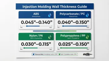
Tolerance guidelines:
- Amorphous polymers: Maintain wall sections within ±25% of nominal thickness
- Semi-crystalline polymers: Tighten tolerance to ±15% due to higher shrinkage rates
Critical insight: Excessively thick walls don't automatically mean stronger parts. They increase cycle time, material cost, and sink mark risk simultaneously. Target the thinnest possible uniform wall within recommended ranges—cooling time scales approximately with the square of wall thickness.
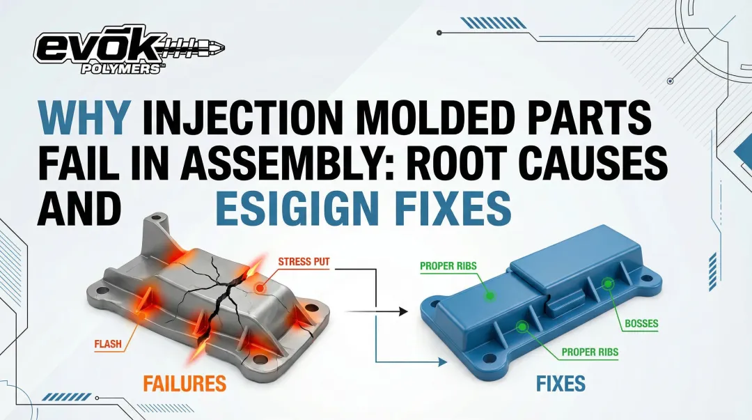
Ribs and Gussets for Structural Stiffness
Ribs allow designers to achieve the stiffness of a thick wall without the drawbacks. Properly designed ribs distribute load across the part geometry instead of concentrating it at one cross-section. However, oversized or poorly placed ribs are a leading cause of sink marks on the cosmetic face of the part.
The physics of rib-induced sink marks: If a rib is too thick, it creates localized thermal mass at the intersection with the nominal wall. Because this thick intersection is insulated by the outer skin, its core remains molten longer. When that core finally cools and shrinks, it pulls the solidified outer skin inward—creating a visible surface depression directly opposite the rib.
Standard DFM rules for rib geometry:
- Rib thickness: 40-60% of nominal wall thickness (reduce to 30% for Class A surfaces)
- Maximum rib height: 2.5 to 3 times the nominal wall thickness
- Rib base fillet: 0.25T to 0.5T radius (where T = nominal wall thickness)
The base fillet eliminates sharp corners and reduces stress concentrations, but must not be so large that it creates a thick, sink-prone mass at the intersection. Taller ribs create deep, narrow mold cavities that are difficult to fill, prone to sticking during ejection, and susceptible to structural buckling under load.
Radii and Fillets at Corners and Transitions
Sharp internal corners are the leading cause of mechanical failure in injection molded parts. They act as mechanical notches that multiply local stress by a significant factor under load—this is called the Stress Concentration Factor (SCF).
The exponential danger of sharp corners:
| Radius-to-Thickness Ratio | Approximate SCF | Risk Level |
|---|---|---|
| 0.1 | ~3.0 | Critical failure risk |
| 0.2 | ~2.5 | High stress |
| 0.4 | ~1.8 | Moderate stress |
| 0.5 | ~1.5 | Industry standard minimum |
| 1.0 | ~1.2 | Optimal stress distribution |
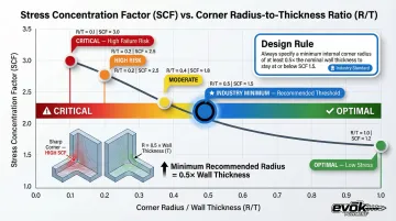
A sharp corner (R/T < 0.2) can multiply local stress by nearly 300%. The design principle: Internal corners should always have the largest radius the geometry allows—minimum internal corner radius of 0.5x wall thickness.
Impact on durability: Studies show that increasing an inside corner radius from 0.010" to 0.020" can improve a part's impact strength by up to 25%. An external radius should also equal the internal radius plus the wall thickness (R_ext = R_int + T) to maintain uniform wall thickness through the turn.
External sharp corners on the part exterior also matter for impact resistance—parts that experience drop or impact loads are especially sensitive to corner geometry.
Draft Angles and Their Effect on Part Integrity
Insufficient draft forces the mold to drag against the part surface during ejection, creating micro-scratches, surface stress, and—in flexible materials—permanent deformation that weakens the part's structural integrity over its service life.
As thermoplastic resin cools inside a mold, it shrinks and compresses tightly around the mold's core. This generates significant compressive friction forces at the part-steel interface. Without sufficient draft (taper) on vertical walls, the part drags against the steel during ejection, causing severe cosmetic and structural defects.
Draft angle recommendations by surface finish:
| Surface Finish | Example Standard | Minimum Draft Angle |
|---|---|---|
| Polished/Smooth | SPI A-1, A-2, A-3 | 1° to 2° (0.5° absolute minimum) |
| Light Texture | SPI D-1, MT-11010 | 3° minimum |
| Heavy Texture | SPI D-3, MT-11030 | 5° to 10°+ |
The industry-standard formula for textured surfaces: Add 1.5° of draft for every 0.001 inches (0.025 mm) of texture depth, on top of the baseline 1° to 2° required for a smooth wall. Textured surfaces create thousands of microscopic undercuts—if the draft angle is too shallow, the plastic cannot clear these micro-undercuts before the part is pushed off the core, destroying the texture.
Gate Location and Its Influence on Weld Lines
Where the gate is placed determines where weld lines (knit lines) form—inherent weak points where two melt flow fronts meet and bond incompletely. Their location relative to stress-bearing areas of the part determines how much they matter.
The mechanism: Weld lines occur when two or more molten polymer flow fronts meet inside the mold cavity. Because plastic flows via "fountain flow," the leading edges of the melt fronts cool rapidly as they contact the mold walls. When these semi-cooled fronts collide, they form a V-shaped notch at the surface.
The deeper problem is molecular: polymer chains at the interface fail to fully entangle and interdiffuse, leaving a boundary held together only by weaker secondary polar bonds.
Quantified strength reduction:
| Material Type | Weld Line Strength Retention | Why It Matters |
|---|---|---|
| Unfilled Amorphous (ABS, PC) | ~75% to 100% of yield strength | Retains yield strength if processed hot, but suffers severe reductions in elongation at break and impact toughness |
| Glass-Fiber Reinforced (e.g., PA66 GF30) | ~40% to 50% of tensile strength | Fibers align parallel to the flow front—when fronts meet, fibers do not cross the weld line, leaving the interface entirely unreinforced |
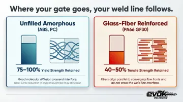
In glass-filled materials, a weld line can reduce local tensile strength by up to 60% compared to the bulk material.
The design strategy: Work with your molder to position gates so weld lines form in low-stress, non-critical zones of the part. Use mold flow simulation to predict where fronts will meet before cutting steel, or implement sequential valve gating in multi-gate systems to control front collision timing and location.
Material Selection as a Design Decision
Material selection should happen concurrently with geometric design, not after. The choice of resin determines the part's baseline tensile strength, impact resistance, fatigue life, UV stability, and chemical resistance—all of which define the ceiling on what good geometry can achieve.
Key resin properties to evaluate for durability:
- Tensile strength: The maximum stress a material can withstand while being stretched before breaking
- Elongation at break: Ductility vs. brittleness—high elongation means the material can deform before breaking; low elongation means brittle failure
- Notched Izod impact strength: Resistance to sudden impact or shock loading
- Heat deflection temperature (HDT): The temperature at which the material begins to deform under a specified load
- Chemical/UV resistance: Ability to withstand specific chemicals or UV exposure the part will encounter in service
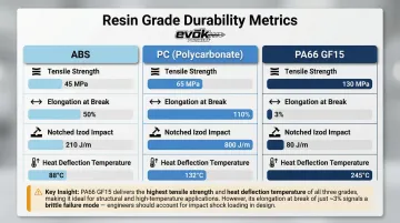
Example baseline durability metrics:
| Material Grade | Tensile Strength (Yield) | Elongation at Break | Notched Izod Impact | HDT (1.8 MPa) |
|---|---|---|---|---|
| ABS | 41.0 MPa | 26% | 3.47 J/cm | N/A |
| PC | 65 MPa | 130% | 65 kJ/m² | 124°C |
| PA66 GF15 | 130 MPa | 3% | 5.5 kJ/m² | 250°C |
The Role of Additives and Fillers
Glass fiber reinforcement, impact modifiers, and UV stabilizers are design-stage decisions that can dramatically extend part life in demanding environments. Each comes with tradeoffs worth understanding before tooling is cut:
- Glass fiber (20–30% loading): Significantly increases tensile strength, flexural modulus, and HDT—but drops elongation dramatically. Adding 20% GF to PA66 raises tensile strength from ~51 MPa to ~111 MPa while reducing elongation at break from ~291% to just 8%, shifting the material from ductile to brittle. Glass fibers are also highly abrasive and accelerate wear on mold cavities, gates, and runner systems.
- Impact modifiers: Rubber-toughening agents added to brittle resins (such as ABS or PC/ABS blends) to improve resistance to sudden shock loads, typically at a modest cost to stiffness and tensile strength.
- UV stabilizers: HALS (hindered amine light stabilizers) or UV absorbers compounded into the resin to prevent surface degradation, chalking, and embrittlement in outdoor or high-UV applications.
Early collaboration with your molder on additive selection matters—particularly for GF-filled grades, where abrasive wear on tooling affects long-term mold maintenance costs.
Why Material Selection Is Truly a Design-Stage Decision
Switching materials after tooling is cut often requires mold modifications, because different resins shrink at different rates. Amorphous plastics (ABS, PC) typically shrink between 0.3% and 0.7%, while semi-crystalline plastics (PP, Nylon) shrink between 1.5% and 3.0%.
Glass-fiber reinforced grades add another layer of complexity: they exhibit anisotropic shrinkage, shrinking significantly less in the direction of flow than transverse to it. This directional variation makes cavity sizing far less forgiving.
If a tool is cut for an unfilled ABS resin and you later switch to a 30% GF-Nylon to solve a strength issue, the part will fail dimensional tolerances, requiring expensive mold rework to resize the cavities, adjust gate sizes, and modify cooling channels.
Common Design Mistakes That Undermine Part Durability
The most common durability-killing design errors include:
- Sharp internal corners with no radius: Creates stress concentrations that multiply local stress by 200-300%
- Abrupt wall thickness transitions: Causes differential cooling, warpage, and residual stress
- Ribs too thick relative to nominal wall: Leads to sink marks, voids, and cosmetic defects
- Insufficient draft on deep draws: Forces excessive ejection stress, causing scratches and deformation
- Gate placement that puts weld lines in high-stress zones: Reduces local strength by up to 60% in glass-filled materials
A persistent trap in part design is assuming thicker always means stronger. That logic leads to over-designed parts with sink marks, internal voids, and residual stress that actually reduce performance. Proper DFM requires understanding the physics of plastic flow, cooling, and solidification, not just adding material.
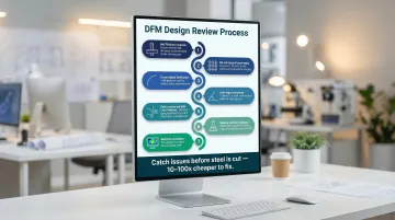
Most of these mistakes stay hidden until the mold is cut and first parts are shot. By then, corrections cost 10-100x more than catching them during design review.
How a Pre-Molding Design Review Catches Durability Issues Early
A pre-molding design review (DFM review) involves systematic analysis of part geometry, material selection, wall thickness, rib design, draft, and gate strategy before any tooling investment is made. Mold flow simulation can predict where weld lines, sink marks, and fill problems will occur, allowing you to relocate gates, adjust wall thickness, or modify rib proportions before cutting steel.
What a thorough DFM review includes:
- Wall thickness analysis and uniformity check
- Rib and gusset proportioning validation
- Internal and external corner radius verification
- Draft angle assessment for all vertical surfaces
- Gate location strategy and weld line prediction
- Material selection validation against end-use requirements
- Mold flow simulation to identify fill, pack, and cooling issues
Each item on that list represents a category where a single overlooked detail can compromise part durability in the field. EVOK's cross-functional team combines industrial design, mechanical engineering, and deep injection molding knowledge to bring multiple perspectives to the review. This matters because a design-only team may approve a rib that looks structurally sound but will create sink marks, and a manufacturing-only team may accept a gate location that puts a weld line directly in a load-bearing zone.
A design review before tooling consistently reduces warranty claims, shortens time to a validated production part, and avoids costly mold modifications down the line.
With over 25 years of experience in injection molding, EVOK has helped OEMs across powersports, medical, semiconductor, and consumer product industries catch these issues early — before they become expensive steel problems.
Frequently Asked Questions
What is the lifespan of an injection mold?
Injection mold lifespan is measured in production cycles, ranging from under 500 cycles for prototype aluminum molds to over one million cycles for hardened steel production molds (SPI Class 101). Proper maintenance and operating conditions are the biggest variables affecting mold longevity.
Are injection molded parts stronger than 3D printed parts?
Injection molded parts are generally stronger and more consistent than FDM 3D printed parts due to isotropic material properties and higher packing density. FDM ABS parts achieve only 65-72% of the tensile strength of injection-molded ABS, though some industrial SLS processes can approach that performance for complex low-volume geometries.
What wall thickness is recommended for injection molded parts?
Ideal wall thickness depends on the material and part geometry. Most structural thermoplastic parts target 0.030" to 0.150" (0.76 to 3.81 mm) depending on resin family. Consistency matters more than a specific number—maintain variations within ±15% for semi-crystalline resins and ±25% for amorphous resins.
How do weld lines affect injection molded part strength?
Weld lines can reduce local strength significantly. In unfilled amorphous plastics, they typically retain 75-100% of yield strength but lose impact toughness; in glass-fiber reinforced materials, tensile strength can drop 50-60% because fibers align parallel to the flow front rather than crossing the interface. Weld lines in high-stress or load-bearing zones are a serious durability concern.
What design changes can prevent warping in injection molded parts?
The primary design-level levers for minimizing warpage include:
- Uniform wall thickness throughout the part
- Balanced rib placement to distribute stiffness evenly
- Material selection matched to the application
- Gradual transitions (3:1 taper ratio) where thickness changes are unavoidable
- Strategic gate location to ensure balanced filling and packing
Can gate location be changed after the mold is built?
Repositioning a gate after tooling is cut is possible but costly, requiring mold steel modification or insertion—often involving electrical discharge machining (EDM) or welding. This reinforces the importance of confirming gate strategy during the design phase before tooling investment, ideally using mold flow simulation to predict weld line locations and optimize gate placement before cutting steel.
Ready to optimize your injection molded part design before tooling? EVOK's team of industrial designers, mechanical engineers, and injection molding specialists can conduct a pre-molding design review to catch durability issues early—saving you time, money, and warranty headaches. Contact us at 612-991-2001 or visit evokpoly.com to get started.