Introduction
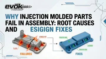
Assembly failures in injection molded parts rank among the costliest quality breakdowns in manufacturing. A part can pass visual inspection at the mold, meet dimensional checks, and still fail at the assembly line — refusing to mate with its counterpart or cracking under snap-fit engagement.
The financial impact follows a predictable escalation. According to the 1-10-100 rule of quality developed by Labovitz and Chang, a defect that costs $1 to prevent in design balloons to $10 when corrected internally and $100 if it reaches the customer.
For injection molded assemblies, that multiplier hits hard: scrap rates climb, assembly labor doubles as workers force non-conforming parts, and field failures trigger warranty claims or recalls.
The good news is that most of these failures share the same short list of root causes: warping from uneven cooling, sink marks at boss locations, weld lines landing on structural features, and insufficient draft angles. Each has a concrete design fix — and nearly all can be caught before tooling is ever committed.
Key Takeaways
- Assembly failures stem from predictable design decisions made before the mold is cut — the root causes are identifiable and preventable
- Four root causes drive 80% of failures: warping, wall thickness variation, weld line misplacement, and inadequate draft
- Design-stage fixes cost roughly 10x less than internal corrections and 100x less than field failures
- At weld lines, glass-filled resins lose 40–60% of their strength — a direct result of fiber misalignment during fill
- Early DFM reviews and mold flow analysis eliminate costly post-tooling rework
Root Causes: Why Injection Molded Parts Fail in Assembly
Assembly failures differ fundamentally from cosmetic defects. The part may look flawless but fail to snap, seat, or align when mated with its counterpart. These failures originate in four design and process root areas that compromise dimensional accuracy, structural integrity, or ejection quality.
Warping and Dimensional Inaccuracy
Warping occurs when uneven cooling rates and non-uniform wall sections cause differential shrinkage, distorting the part's geometry after ejection. Thicker sections cool more slowly, experiencing prolonged molecular relaxation and higher residual stresses that pull surrounding material out of plane.
How warped parts fail in assembly:
- Gaps appear at mating interfaces where flat surfaces no longer make contact
- Mounting holes shift out of alignment, preventing fastener insertion
- Snap-fit arms deflect incorrectly, refusing to engage or breaking on first assembly
- Flatness deviations prevent proper seating on PCBs or structural frames
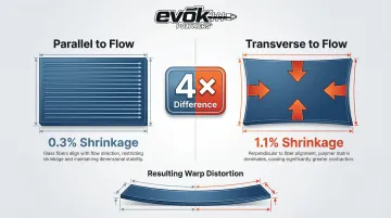
Glass-filled materials amplify this problem. Fibers align parallel to melt flow, restricting thermal contraction along the flow path while forcing higher shrinkage transverse to flow. 30% glass-filled PBT shrinks just 0.3% parallel to flow but 1.1% transverse—a nearly 4x difference that guarantees warpage in flat panels or thin-walled housings.
Wall Thickness Variation and Sink at Interface Surfaces
Abrupt transitions in wall thickness create thermal mass imbalances. Thicker sections—particularly at bosses, ribs, and snap-fit tab bases—cool more slowly than surrounding walls, pulling surface material inward and creating visible sink marks or internal voids.
Industry standards for rib-to-wall ratios:
- Untextured appearance parts: Maximum 30% of nominal wall thickness
- Textured appearance parts: Maximum 50%
- Structural parts (where sink is acceptable): 75–85%
Sink at a boss reduces the effective contact surface for press-fit inserts, causing threaded inserts to loosen under torque or self-tapping screws to strip. Sink at snap-fit tab bases creates internal voids that reduce the tab's flexural strength, causing fracture on first deflection load.
Weld Lines at Structural Assembly Features
Weld lines form where two melt flow fronts meet in the mold cavity. At this interface, molecular chains don't entangle fully, creating a zone of poor bonding and a "V" notch stress concentrator.
The strength losses are significant. Glass-filled polycarbonate loses up to 50% of its tensile strength at weld lines compared to bulk material. Glass and talc-filled polypropylene suffers a 40–60% reduction in ultimate tensile strength because fibers align parallel to the weld interface rather than crossing it for reinforcement.
When weld lines land on snap-fit arms, pin boss walls, or alignment rib bases, those features become pre-cracked. Parts fracture on first assembly or fail prematurely under service loads—within hours of installation.
Insufficient or Incorrect Draft Angles
Parts with inadequate draft resist clean ejection from the mold. As ejector pins push the part forward, it drags against cavity walls—creating surface scratches, tearing, and dimensional distortion. The part arrives outside its tolerance envelope before it ever reaches assembly.
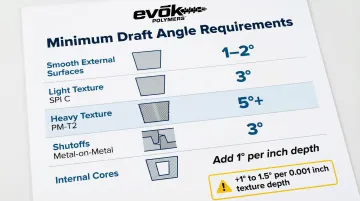
Minimum draft angle requirements:
- Smooth external surfaces: 1–2° minimum
- Light texture (SPI C / PM-T1): 3° minimum
- Heavy texture (PM-T2): 5° or more
- Internal cores: Add 1° per inch of depth
Texture rule: Add 1° to 1.5° of draft for every 0.001 inches of texture depth to clear microscopic undercuts.
The downstream effects are direct: undersize bores won't accept press-fit inserts, oversize pins won't snap into receptacles, and surface drag on cosmetic mating faces creates visible gaps after assembly.
What Happens When Assembly Failures Go Unaddressed
The cost spiral compounds quickly. Scrap rates climb as non-conforming parts are rejected. Assembly labor time doubles as workers attempt to force misaligned parts or manually rework features. Line throughput drops, delaying shipments and triggering expedite fees.
Field failures escalate costs exponentially. According to the American Society for Quality, total quality costs can consume 15% to 40% of annual revenue, with external failure costs (warranty claims, recalls, customer returns) representing the largest share.
Those external failure costs are only part of the picture. Upstream rework carries its own steep price tag: once tooling is cut, mold rework costs 10x to 100x more than fixing the design beforehand. Moving a hot runner drop or gate location post-tooling can cost $10,000 per cavity, and adding draft to a textured surface may require re-cutting the entire cavity.
Warning Signs Your Parts Are Heading Toward Assembly Failure
Several early signals—visible before a single assembly attempt—indicate downstream failure:
- Visible warpage when the part is placed on a flat surface; gaps or bow in nominally flat sections
- Sink marks at boss locations, snap-fit tab bases, or rib junctions—indicating wall thickness problems that compromise joint integrity
- White stress marks or surface cracking on snap-fit arms immediately after ejection—a sign of insufficient draft, overpacking, or weld line proximity at high-stress locations
Design Fixes: How to Engineer Parts That Survive Assembly
The most effective time to prevent assembly failures is during part and tool design—before any steel is cut. Each fix below addresses one or more root causes identified above.
Enforce Uniform Wall Thickness Across Assembly-Critical Sections
Walls should remain within the material manufacturer's recommended thickness range, with gradual transitions (tapered, not stepped) between sections to prevent differential cooling.
General guideline: Ribs should be 50–60% of the nominal wall thickness at their base to avoid sink at the attachment point. For bosses accepting threaded inserts, the outer diameter should be 2.0 to 2.5 times the insert diameter, with material beneath the insert at least 1/6th the insert's diameter.
When to implement: During initial 3D modeling, before DFM review. Flag all boss, rib, and snap-fit features for wall thickness compliance as a standard checkpoint.
Strategically Place Gates to Control Weld Line Location
Gate placement directly determines where flow fronts meet and therefore where weld lines form. By intentionally locating gates so weld lines fall in low-stress, non-assembly-critical zones (hidden interior surfaces, away from snap arms and pin bosses), designers substantially reduce structural risk without changing part geometry.
Validated mitigation: A 2022 Moldex3D study demonstrated that adding an offset overflow well forces "underflow" across the weld line, reorienting glass fibers. This increased the major modulus at the weld line from a 35% deficit to just 16% less than bulk material.
Run Mold Flow Analysis Before Tooling Commitment
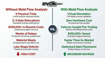
Mold flow analysis simulates fill, pack, cooling, and shrinkage—predicting warpage, sink, weld line location, and air trap formation before the mold is cut. This allows the design team to test gate locations, wall thickness adjustments, and cooling channel configurations virtually.
ROI of virtual tryouts: One documented case eliminated 6 physical mold trials and avoided 2–3 post-tooling gate relocations, saving over $100,000.
EVOK's pre-molding design review process includes mold flow studies specifically structured to identify these failure modes before tooling investment, reducing risk on large-scale projects where assembly performance is non-negotiable.
Conduct Tolerance Stack-Up Analysis for Multi-Part Assemblies
Every injection molded part carries dimensional variation from shrinkage and process conditions. In multi-part assemblies, these individual tolerances stack up. If the combined tolerance of all mating parts exceeds the designed clearance or interference fit, assembly failure is guaranteed by geometry alone, no matter how precisely each individual part is produced.
Two approaches exist for this analysis, and choosing the right one matters:
- Worst-Case tolerancing assumes all parts hit their extreme limits simultaneously — which forces unnecessarily tight (and expensive) manufacturing tolerances
- Root Sum Square (RSS) assumes a normal distribution of variation, allowing designers to safely expand individual part tolerances while maintaining a 99.7% probability of successful fit
When to perform: At the design phase, before first articles are in hand. Include baseline shrinkage data for the selected resin (for example, 30% GF PBT: 0.3% parallel to flow, 1.1% transverse).
Apply Proper Draft Angles to All Vertical Faces and Cores
Validating draft before DFM sign-off prevents ejection-induced distortion and ensures the part holds its dimensional profile through the ejection stroke.
Draft angle minimums:
| Surface Type | Minimum Draft |
|---|---|
| Smooth external surfaces | 1–2° (0.5° absolute minimum) |
| Light texture (SPI C) | 3° |
| Heavy texture (PM-T2) | 5° or more |
| Shutoffs (metal-on-metal) | 3° |
| Internal cores | Add 1° per inch of depth |
Cores and internal features require more draft than external walls because material shrinkage wraps around the core during cooling, increasing drag during ejection.
Long-Term Prevention: Building Assembly-Readiness Into Every Project
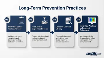
Recurring assembly failures rarely trace back to a single bad part. They trace back to gaps in process—missed DFM reviews, undocumented failures, tooling drift that goes undetected until it hits the line. These four practices close those gaps:
- Run a DFM gate before tooling release — Review wall thickness uniformity, gate placement vs. assembly features, draft compliance, and tolerance stack-up as a mandatory checklist
- Keep first-article inspection records — CMM-measure all assembly-critical features (boss diameters, snap-fit arms, mating surface flatness) so tooling wear drift gets caught before the assembly line does
- Document every assembly failure in a lessons-learned library — note which feature failed, which root cause applied, and which fix worked, then feed that back into future design reviews
- Treat mold flow analysis as a required deliverable on all new tooling programs, not just complex geometries, so gate and weld line placement is always backed by data
According to one DFM analysis, rigorous DFM reviews can reduce mold costs by 20–50% and push first-shot success rates to 98%, compared to the industry average of 65%.
Conclusion
Assembly failures in injection molded parts are not random. They trace to specific, preventable decisions in part design, gate placement, wall thickness, and tolerance planning. Catching these issues before tooling is committed returns far more than any downstream fix — DFM reviews, mold flow analysis, and tolerance stack-up planning are the three levers that matter most.
Skip those steps, and the costs compound fast:
- Scrap rates climb as out-of-tolerance parts pile up
- Assembly labor doubles when fits require manual adjustment
- Production schedules slip while tooling corrections are made
- Field failures erode customer trust in ways that are hard to recover from
The engineering principle holds: design-phase prevention is orders of magnitude cheaper than internal correction, and far cheaper than external failure. Teams that front-load DFM and mold flow analysis — the approach Evok builds into every project — consistently close the gap between first article and production-ready parts.
Frequently Asked Questions
What is the most common reason injection molded parts fail during assembly?
Dimensional inaccuracy from warping, sink marks at assembly features, and weld lines at structural interfaces account for the majority of failures. All three typically originate in part design decisions—non-uniform wall thickness, poor gate placement, or inadequate draft—made before tooling is cut.
How does warping in an injection molded part affect assembly?
Warping changes the part's geometry after ejection, causing mating surfaces to gap, mounting holes to misalign, and snap features to miss their designed engagement. Non-uniform wall thickness and uneven cooling are the primary drivers—particularly severe in glass-filled resins, where transverse shrinkage can be 4x greater than parallel shrinkage.
Can gate placement cause assembly failures?
Yes. Gate placement determines where weld lines form. If weld lines land on snap-fit arms, boss walls, or alignment ribs, those features lose 40–60% of their tensile strength and become prone to fracture on first assembly or under service loading.
What is tolerance stack-up and why does it matter for injection molded assemblies?
Tolerance stack-up is the cumulative effect of dimensional variation across all parts in an assembly. When stacked tolerances exceed the designed fit allowance, parts won't assemble correctly—even if each component passes individual inspection. RSS statistical tolerancing addresses this by modeling normal variation distribution rather than assuming worst-case on every dimension.
When in the design process should injection molding assembly failures be addressed?
The design phase—before any tooling is committed—is the correct time. Design changes cost a fraction of mold rework, and tools like mold flow analysis allow virtual testing of gate placement, wall thickness, and shrinkage behavior at zero hardware cost.
How can a DFM review help prevent assembly failures in injection molded parts?
A DFM (Design for Manufacturability) review evaluates wall thickness uniformity, draft angles, gate location, and rib/boss geometry against material and process constraints. It catches the most common root causes—warping, sink, weld line misplacement, and ejection distortion—before they're locked into tooling.