Introduction
Draft angles are essential to successful injection molding. Without them, parts won't release properly from the mold.
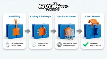
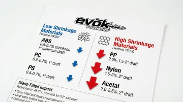
When thermoplastics cool from their molten state, they undergo significant shrinkage—ranging from 0.5% for materials like Polycarbonate to over 2.5% for semi-crystalline resins like Acetal. This shrinkage creates immense compressive forces against mold cores, generating friction that can exceed acceptable ejection forces by 10 times without proper draft.
Insufficient draft leads to serious manufacturing problems:
- Drag marks and scuffing that ruin cosmetic appearance
- Warpage from excessive ejection stress
- Cycle times that increase by 15-30%
- Accelerated mold wear reducing tooling lifespan by 5-8%
Conversely, excessive draft can compromise part function by affecting mating surfaces, assembly tolerances, and aesthetic requirements for vertical walls.
This guide covers what draft angles are, why they're critical, standard calculation methods, specification practices, and common design pitfalls to avoid. Whether you're designing your first injection molded part or optimizing an existing product, understanding draft angle fundamentals will help you balance manufacturability with design intent.
TLDR: Key Takeaways on Injection Molding Draft Angles
- Apply slight taper to vertical walls (draft angle) to enable clean ejection and prevent surface damage
- Use 1-2° baseline for smooth surfaces; textured surfaces need +1-1.5° per 0.001" depth
- Proper draft reduces cycle time by 30% while preventing drag marks, warpage, and mold wear
- Requirements depend on surface finish, material type, wall depth, and feature location
What Draft Angle Represents in Injection Molding
Draft angle is the degree of taper applied to surfaces parallel to the direction of mold opening (draw direction). Designers measure this taper in degrees from the vertical axis. It serves a critical mechanical function: counteracting plastic shrinkage during cooling, which causes parts to grip tightly onto mold cores and cavity walls.
As molten plastic cools and solidifies, it contracts around the mold core, creating compressive stress and friction. Without draft, the part maintains continuous contact with the mold wall throughout ejection, generating high resistance that can damage both the part and tooling.
Draft angles solve this by ensuring the part separates from the mold surface immediately upon ejection, eliminating friction after the initial break and reducing ejection forces by 60-80%.
Draft is not optional for injection molded parts—it's a design requirement for all applications. The only exceptions involve specific soft, flexible materials that can stretch during ejection without damage, though even these typically benefit from minimal draft.
During ejection, the taper allows the part to separate progressively as ejector pins push it out. This gradual release prevents vacuum formation between high-gloss surfaces and the cavity, which would otherwise require excessive force and potentially deform the part.
Beyond its mechanical role, draft functions as both a design parameter and a manufacturing variable:
- Design parameter: Specified during part design in CAD software
- Manufacturing variable: Affects tooling complexity and process optimization
- Documentation requirement: Industry standards like DIN 16742:2013-10 require draft as an integral component of design documentation
The standard defines drafts as "production-induced inclinations on the molded part in the demolding orientation of moving tool parts."
Factors That Influence Draft Angle Requirements
Optimal draft is not a single universal value but depends on multiple interrelated design and manufacturing factors. Understanding these variables allows engineers to specify appropriate draft angles that balance manufacturability with functional requirements.
Surface Finish and Texture Depth
Polished surfaces (SPI-A1, A2) create minimal friction and can work with 0.5-1° draft on shallow features. These mirror-like finishes allow parts to release easily, though they can create vacuum seal risks that require careful ejection system design.
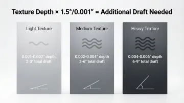
Textured surfaces create microscopic mechanical undercuts that dramatically increase ejection resistance. The industry standard calculation adds 1 to 1.5 degrees of draft for every 0.001 inches (0.025mm) of texture depth. Light textures (PM-T1) typically need 3° minimum, while heavy textures (PM-T2) require 5° or more.
A texture depth of 0.003" requires: 0.003" × 1.5°/0.001" = 4.5° additional draft beyond baseline. Specific texture patterns from providers like Mold-Tech have precise requirements—a texture depth of 0.006" (MT-11100) requires 9° draft to prevent the texture peaks from hooking onto the mold during ejection.
Material Shrinkage Characteristics
Materials with higher shrink rates contract more tightly onto cores than low-shrink materials. Polypropylene shrinks approximately 2%, gripping the mold aggressively, while ABS shrinks only 0.5-0.7%, naturally aiding ejection.
Material structure impacts draft requirements:
- Semi-crystalline materials (PP, Nylon, Acetal) need more draft than amorphous materials (ABS, PC, PS)
- Higher shrinkage rates create less uniform contraction patterns
- Crystalline structures grip mold cores more aggressively as molecular chains arrange into ordered formations
Glass-filled or reinforced materials present unique challenges. While 30% glass fiber reduces PA66 shrinkage from 3.0% to approximately 0.5%, the resulting materials are stiffer, more abrasive, and less compliant.
Glass-filled materials often require larger draft angles (minimum 1.25° for glass-filled ABS) despite lower shrinkage. They cannot stretch during ejection and cause accelerated mold wear.
Wall Depth and Feature Height
Deeper walls have more surface area in contact with the mold, creating proportionally more friction. The guideline: add approximately 1 degree of draft for every inch of wall depth beyond the baseline 2 inches.
A part with 4-inch deep walls should have at least 3-4° of draft even with smooth finish: 2° baseline + (4-2) × 1° = 4° total recommended draft. Deep draw features—where depth exceeds 2-3 times the opening width—require especially careful draft planning to prevent seizure during ejection.
Internal Versus External Surfaces
Internal surfaces (cores, holes, pockets) shrink onto the mold core and require more draft than external surfaces. As plastic cools, it contracts inward, gripping cylindrical cores and internal features tightly.
External surfaces shrink away from the cavity, naturally aiding ejection and allowing for less aggressive draft. Recommended starting points: 1.5-2° minimum for internal features versus 1° minimum for external features. This differential accounts for the mechanical advantage of shrinkage direction.
Part Geometry Complexity
Ribs, bosses, gussets, and louvers all need individual draft consideration on their vertical faces. Ribs should have 0.5-1.0° per side to prevent sink marks on opposite surfaces, while maintaining thickness at 50-60% of nominal wall.
Bosses require similar draft considerations (0.5-1.0° per side) and should connect to walls with ribs or gussets for stability rather than standing alone. Undercuts, side actions, and lifters may limit available draft angles in certain directions, requiring careful coordination between draft application and mold opening direction.
Standard Draft Angle Guidelines and Calculations
While every part is unique, industry-standard baselines provide reliable starting points for most applications. These guidelines have been developed through decades of manufacturing experience and proven across millions of production parts.
Baseline Draft Recommendations
1 to 2 degrees serves as the universal starting point for any vertical wall with smooth finish and depth up to 2 inches.
One degree is often sufficient for shallow, non-critical features, while 2 degrees provides better margin for process variability and material behavior differences.
0.5 degrees represents an absolute minimum for design-critical features where straight walls are essential, but this compromises manufacturability.
Parts with 0.5° draft require careful mold maintenance and may experience shorter production runs before surface degradation affects part quality.
At EVOK, we recommend 1° as the preferred minimum on surfaces. In tight areas where sizing is critical, we can achieve as low as 0.25°. In some cases, no draft or even reverse draft with small undercuts is possible, depending on geometry and material deflection characteristics.
Draft Calculations for Textured Surfaces
The basic rule: add 1-1.5° per 0.001" texture depth beyond your baseline draft.
Texture-specific guidelines:
- Light texture (0.001-0.002" depth): 2-3° total draft
- Medium texture (0.002-0.004" depth): 3-6° total draft
- Heavy texture (0.004-0.006" depth): 6-9° total draft
Calculation example: 0.003" texture depth × 1.5°/0.001" = 4.5° additional draft needed beyond baseline.
Always consult texture specification sheets and add draft conservatively for first-time textures. Actual requirements vary based on pattern geometry and orientation. This matters especially for deep features, where texture compounds friction challenges.
Adjustments for Deep Draw Features
"Deep draw" refers to features where depth exceeds 2-3 times the opening width. These features require stepped calculation:
2° baseline + (depth in inches - 2) × 1° = total recommended draft
Example: For a 5-inch deep pocket: 2° + (5-2) × 1° = 5° total draft recommended. This accounts for the cumulative friction across the extended surface area and ensures the part can release without excessive ejection force.
Special Considerations for Metal-on-Metal Mold Contacts
When mold components slide against each other—such as slides, lifters, or cam actions—3° minimum draft is typically required. This prevents galling and seizing of precision mold components during repeated cycles, protecting the substantial investment in complex tooling.
Direction of Draft Application
Draft must always taper in the direction of mold opening: toward the parting line on external surfaces, away from cores on internal surfaces. Applying draft in the wrong direction creates undercuts that prevent mold opening or require expensive side actions.
For parts with mid-plane parting lines, draft must be applied on both sides of the parting line in opposite directions. This creates a subtle taper change at the parting line that should be evaluated for aesthetic and functional impact during design review.
How Draft Angles Are Specified and Validated
Draft specification is a collaborative process between designer, mold maker, and manufacturer during Design for Manufacturing (DFM) review. Proper specification and validation before tooling investment prevents costly modifications and production delays.
Design Documentation and CAD Modeling
Draft should be explicitly called out in engineering drawings with degree measurements and direction indicators. Vague notes like "add draft as required" create ambiguity—leading to mismatched expectations between design intent and manufacturing reality.
CAD modeling should build in draft from the start rather than as an afterthought. Modern CAD software includes draft analysis tools that visualize draft angles across part surfaces, identifying positive, negative, and insufficient draft regions.
Popular tools include:
- SolidWorks' Draft Analysis tool — Color-codes surfaces based on draft adequacy
- PTC Creo's Mold Analysis Extension — Performs 3D thickness checks and simulates injection molding processes
Draft direction should align with the intended parting line and mold opening direction. Establishing these parameters early prevents redesign when the part transitions from prototype to production tooling.
DFM Analysis and Mold Flow Simulation
Design for Manufacturing reviews analyze draft adequacy before tooling investment, identifying potential ejection problems and recommending design changes. Mold flow analysis software can predict ejection forces and identify areas where insufficient draft may cause problems.
Leading simulation platforms:
- Autodesk Moldflow — Predicts volumetric shrinkage at ejection, identifying potential sink marks and ejection difficulties
- Moldex3D — Simulates Flow, Pack, Cool, and Warp to determine optimal ejection timing
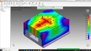
EVOK's DFM process reviews draft angles alongside wall thickness, gate location, and material selection before tooling begins. Using Autodesk Moldflow Insight, we conduct mold filling analysis that shows fill time distribution across mold geometry—ensuring uniform filling and catching potential defects before cutting steel.
Physical Validation During Sampling
First article samples reveal whether draft is adequate through inspection of surface finish and ejection marks. Drag marks, scuffing, or deformation during ejection indicate insufficient draft requiring mold modification—an expensive correction that can delay production by weeks.
At EVOK, our First Article Qualification Process includes 30 inspection points per cavity for all critical dimensions and 5 inspection points per cavity for non-critical dimensions. This comprehensive validation ensures draft angles perform as designed before committing to full production runs.
Consequences of Insufficient or Excessive Draft
Getting draft wrong carries significant cost and quality implications. Understanding these consequences helps justify the engineering time required to optimize draft during the design phase.
Problems Caused by Insufficient Draft
Insufficient draft creates multiple manufacturing and quality problems:
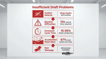
Surface defects — Vertical drag marks, scuffing, and scratches ruin cosmetic appearance and may require secondary finishing. These defects occur when the part scrapes against the mold wall during ejection, particularly in textured parts where the texture "hooks" onto the mold.
Ejection difficulties — Parts stick in the mold, requiring excessive ejector pin force that leads to punctures, deformation, or breakage. Without proper draft, ejection forces can spike to 10 times normal levels, while implementing 1° draft can reduce these forces by over 30% for materials like ABS and PC.
Increased cycle times — Stuck parts require manual intervention or slower automated ejection. Parts that stick can increase cycle times by 15-30%, adding seconds per cycle that multiply across thousands of parts into substantial production delays.
Accelerated mold wear — Constant high-friction ejection degrades polished surfaces and textured finishes. Studies show that increasing draft from 0.5° to 1.5° can reduce ejector pin wear by 67%.
Chronic ejection issues can reduce overall mold lifespan by 5-8%, leading to premature tooling replacement costs that are 3-5 times higher than standard maintenance.
- Part warpage and dimensional instability — High ejection stresses cause parts to warp or distort after removal. The stress concentration from forced ejection can permanently deform thin-walled sections or create residual stresses that manifest as warpage during post-molding cooling.
When Excessive Draft Becomes a Problem
While "more draft is better" generally holds true for manufacturability, there's a point where excessive draft compromises part function.
Draft conflicts with functional requirements when it affects mating surfaces that require precise alignment, assembly tolerances that depend on parallel walls, or aesthetic requirements for vertical surfaces.
Examples include enclosure designs where excessive draft creates visible gaps at assembly interfaces, mounting features where draft prevents proper fit with mating components, and consumer products where aesthetic expectations demand near-vertical walls.
Balancing functional requirements with manufacturing needs requires early collaboration between design and manufacturing teams. This collaboration helps negotiate tolerances and understand what can be realistically achieved with molded parts—finding optimal solutions that satisfy both form and function.
Common Draft Angle Design Mistakes to Avoid
These practical lessons learned from thousands of injection molded parts help designers avoid costly errors that delay production and increase tooling costs.
Assuming Zero Draft is Acceptable
"Perfectly vertical" walls in CAD rarely translate to successful molding without draft.
The misconception that soft or flexible materials don't need draft persists despite evidence that compliant materials benefit from draft to reduce ejection stress and cycle time.
As little as 0.5° is substantially better than 0° when design constraints are severe. Zero draft guarantees high ejection forces, accelerated mold wear, and potential part damage—problems that worsen over production runs of thousands or millions of parts.
Ignoring Draft on Secondary Features
Ribs, bosses, and gussets are often overlooked for draft even when main walls are properly drafted. These features fail first during ejection if undrafted because their thin cross-sections concentrate ejection stress, making them prone to breakage or deformation.
Ribs should have 0.5-1.0° draft per side with thickness maintained at 50-60% of nominal wall to prevent sink marks. Bosses require similar treatment with 0.5-1.0° per side, and should connect to walls with supporting ribs rather than standing alone.
Applying Draft in Wrong Direction
Drafting away from the parting line instead of toward it on external surfaces creates undercuts that prevent mold opening.
This fundamental error requires expensive side actions, lifters, or complete mold redesign to correct.
The rule is simple: external surfaces draft toward the parting line (getting larger as they approach the parting line), while internal surfaces draft away from cores (getting larger as they move away from the core). Violating this principle creates mechanical impossibilities in mold opening.
Not Accounting for Texture Early
Adding texture late in the design process without revisiting draft angles is a common and expensive mistake. A design with 1° draft that works perfectly for smooth surfaces will fail completely when 0.004" texture is added, which requires 6-7° total draft.
Specify texture type and depth during initial design so adequate draft is built in from the start. EVOK's texture specification guide provides minimum draft requirements for 16 different patterns ranging from 1° for fine textures (MT-11000) to 9° for heavy textures (MT-11100), allowing designers to make informed decisions during the concept phase.
Over-Specifying Precision Without Understanding Trade-offs
Demanding perfectly straight walls without recognizing the manufacturing implications creates conflict between design intent and production reality. Designers should communicate functional requirements—why walls must be vertical—so engineers can propose optimal draft solutions that satisfy the underlying need.
Creative solutions that meet functional requirements include:
- Localized zero-draft sections where parts mate
- Draft reversals that maintain parallel surfaces at specific heights
- Split-line adjustments that allow adequate draft while preserving critical dimensions
Conclusion
Draft angle is a non-negotiable design requirement for successful injection molding, not a "nice-to-have" feature.
Proper draft directly impacts multiple critical factors:
- Part quality — Prevents surface defects like drag marks and scratches
- Production efficiency — Reduces cycle times by up to 30%
- Tooling longevity — Minimizes mold wear and extends tool life
- Manufacturing cost — Eliminates expensive mold modifications
Optimizing draft angles during the design phase delivers value throughout the product lifecycle. Parts eject cleanly, molds last longer, production runs faster, and quality remains consistent across millions of cycles.
Getting draft right requires early collaboration between product designers and injection molding partners. EVOK's team uses comprehensive DFM analysis (including Autodesk Moldflow simulation) to optimize draft angles before tooling investment, helping ensure parts are designed correctly the first time while balancing manufacturability with design intent.
Frequently Asked Questions
What is a draft angle?
A draft angle is a slight taper (typically 1-2 degrees) applied to vertical walls parallel to the mold opening direction, allowing molded parts to release cleanly from the mold without damage or excessive friction. This taper compensates for plastic shrinkage during cooling and reduces ejection forces by 60-80%.
Why do we add draft angles to injection molded parts?
Draft compensates for plastic shrinkage, which causes parts to grip mold surfaces tightly as they cool and contract. Proper draft prevents surface defects like drag marks, reduces mold wear by 5-8%, and improves cycle times by up to 30%.
What is the recommended draft angle for injection molding?
Start with 1-2° for smooth surfaces up to 2 inches deep, then add 1-1.5° per 0.001" texture depth for textured surfaces and 1° per inch beyond 2 inches. Internal surfaces require 1.5-2° minimum versus 1° for external surfaces.
How to determine draft angle?
Begin with 1-2° for smooth surfaces, then adjust for texture depth (+1-1.5° per 0.001"), wall depth (+1° per inch beyond 2"), and material type (semi-crystalline like PP needs more than amorphous like ABS). Validate through DFM review and mold flow analysis before tooling.