Have you ever invested heavily in tooling, only to face costly modifications, production delays, or dimensional failures during sampling? Tooling mistakes are expensive and often preventable.
The American Mold Builders Association (AMBA) represents nearly 300 U.S. mold manufacturers, generating over $2 billion in annual tooling sales. This scale shows how vital mold design is to American manufacturing and when mold design fails, companies face delays and cost overruns.
The problem usually starts early. Teams move too quickly through mold design without defining part geometry tolerances, material behavior, cooling strategy, or expected production volume. Weak mold design decisions lead to rework, flash issues, warpage, inconsistent cycle times, and premature tool wear.
The solution lies in structured mold design planning, simulation-driven validation, and precision engineering before steel is cut.
In this guide, you will learn how to approach mold design strategically, avoid costly mistakes, and move confidently from concept to production.
Key Takeaways
Accurate shrinkage compensation and tolerance validation protect assembly fit and reduce costly rework.
Simulation-driven, lifecycle-focused mold design significantly lowers risk, downtime, and total cost of ownership.
Balanced cooling, runner systems, and venting directly control cycle time, scrap rate, and dimensional consistency.
Structural integrity in mold design prevents flash, misalignment, and premature tool wear under high clamping forces.
Mold design decisions made before steel cutting determine the tooling success and long-term production stability.
What Is Mold Design? Understanding the Engineering Behind the Tool
Mold design is the engineering process of creating the tool used to manufacture plastic parts. It includes cavity layout, cooling system planning, runner design, ejection strategy, and structural tool architecture.
Unlike injection molding, which is the production process, mold design defines how the tool will function before steel is cut.
Effective mold design focuses on:
Tolerance control
Shrinkage compensation
Part geometry evaluation
Tool strength and alignment
Repeatable production performance
A disciplined mold design phase reduces risk before manufacturing begins. To achieve this, teams must understand why mold design directly impacts production success.
How Mold Design Impacts Part Quality, Cost, and Production Efficiency?
Mold design determines how consistently parts meet specifications.
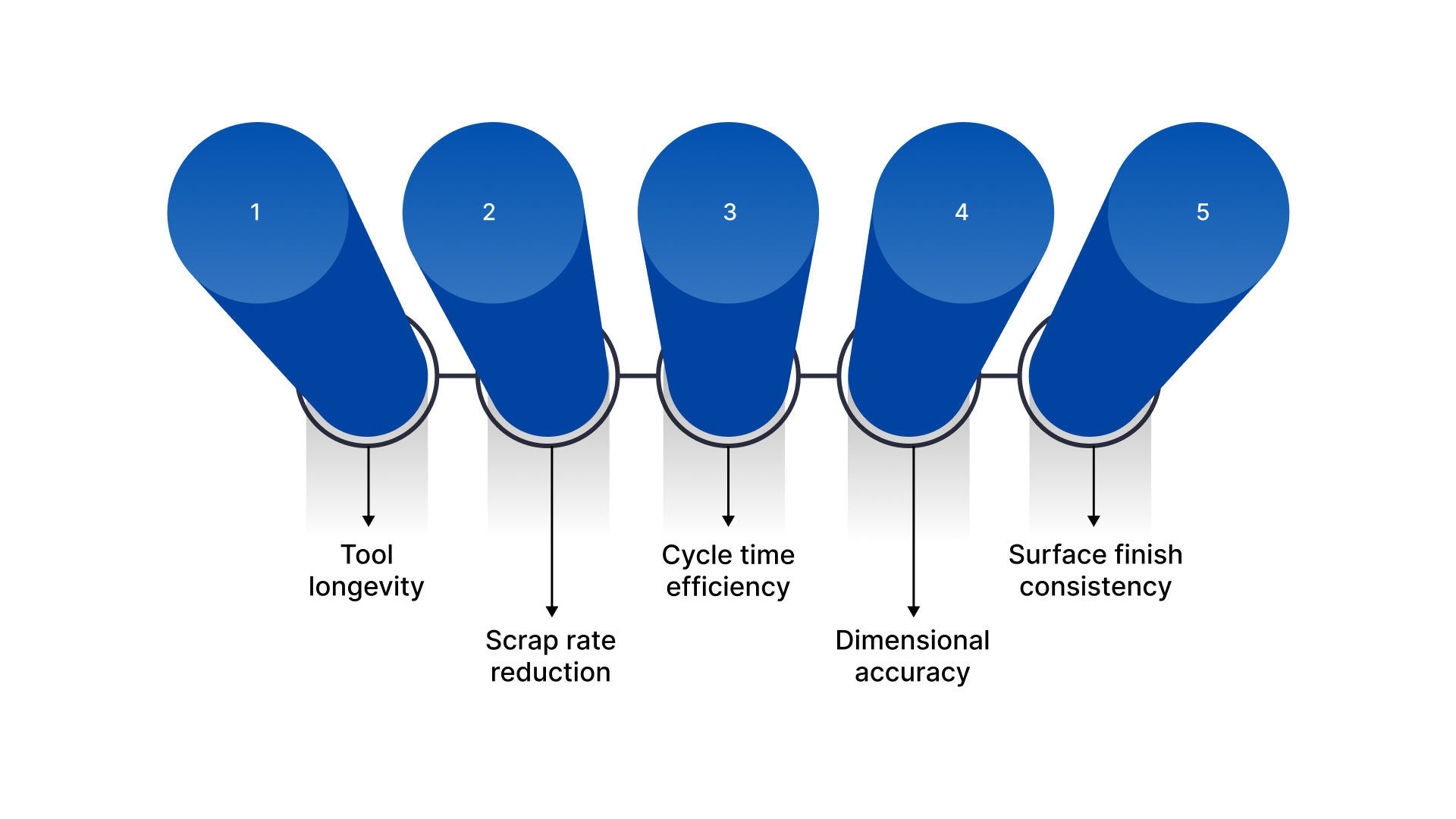
Strong mold design improves:
Tool longevity: Proper steel selection, balanced cooling, and optimized load distribution reduce wear, thermal fatigue, and mechanical stress. It extends tool life and minimizes unplanned repairs.
Scrap rate reduction: Balanced gating, controlled venting, and uniform filling prevent short shots, burn marks, and voids. Consistent part formation lowers rejection rates and material waste.
Cycle time efficiency: Optimized cooling channel layout and heat transfer design remove heat evenly and quickly. Faster, stable cooling shortens cycle time without compromising part quality.
Dimensional accuracy: Accurate shrinkage calculations, uniform packing pressure, and proper venting reduce warpage and distortion. Parts stay within tolerance across long production runs.
Surface finish consistency: Controlled flow paths, venting, and cavity surface treatment prevent flow lines, weld lines, and blemishes. It ensures repeatable cosmetic quality.
Poor mold design increases flash, warpage, sink, and weld line defects. It also drives higher maintenance costs and early tool failure.
Before starting mold design, engineers must clearly define product and manufacturing requirements.
Defining Product Requirements Before Starting Mold Design
Every successful mold design starts with verified, measurable input data, not assumptions.
Engineers should confirm:
Material selection and shrink rates: Identify the exact resin grade, filler content, and supplier data sheet. Review published shrink rates and validate them through past production data or mold flow simulation. Confirm processing temperature range and viscosity behavior to ensure the mold design accounts for shrinkage, flow, and cooling characteristics.
Annual production volume: Define expected yearly output and total lifecycle volume. Confirm with sales forecasts and customer agreements. High-volume programs require hardened steel, strong cooling, and automation-ready mold design, while lower volumes may allow cost-optimized tooling decisions.
Tolerance expectations: Review 2D drawings and 3D CAD models for critical dimensions. Identify tight tolerances and functional fits. Confirm measurement standards and inspection methods so the mold design supports dimensional stability across full production runs.
Cosmetic surface requirements: Define SPI finish standards, texture specifications, or paint-grade surfaces. Confirm which surfaces are visible and customer-facing. The mold design must address gate placement, venting, and flow paths to prevent cosmetic defects.
Structural load demands: Review mechanical performance requirements such as impact resistance, load-bearing areas, and wall thickness. Confirm testing standards and use-case conditions. The mold design must support proper material flow and packing to maintain structural integrity.
Without these verified inputs, mold design decisions become guesswork. A structured engineering review ensures the mold design aligns with performance, durability, and cost goals.
Core Engineering Principles That Govern Successful Mold Design
Strong mold design relies on proven technical fundamentals that directly influence part quality, cycle stability, and long-term tool performance.
The core principles include:
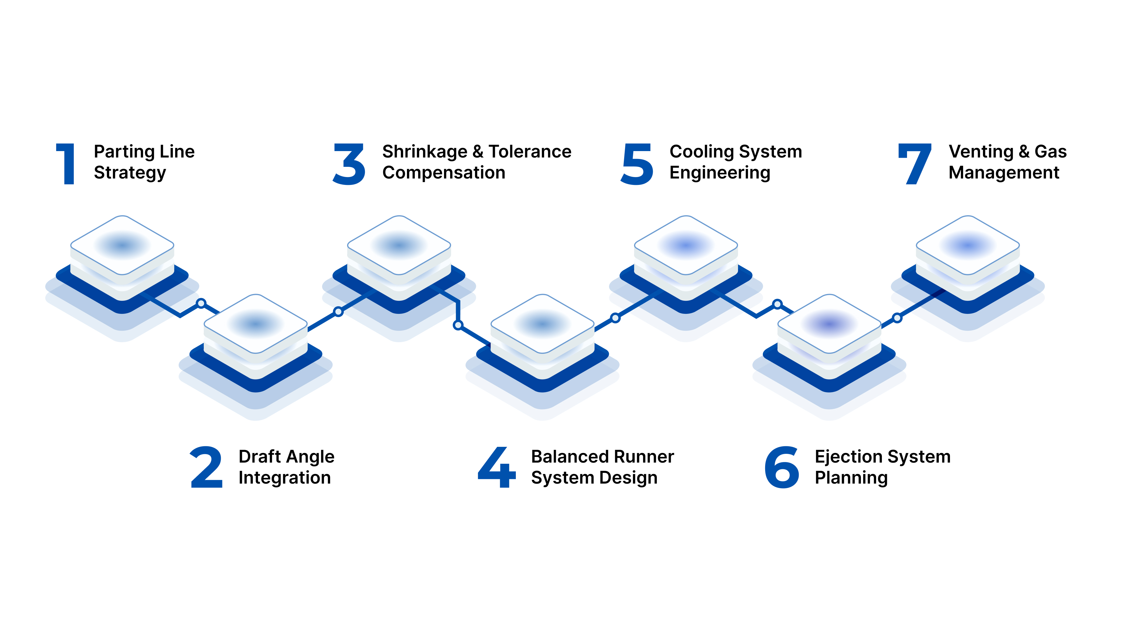
1. Parting Line Strategy
Define parting lines based on geometry, undercuts, and cosmetic priorities. Proper placement simplifies machining, improves sealing, reduces flash formation, supports venting, and lowers long-term maintenance risks during repeated production cycles.
2. Draft Angle Integration
Incorporate appropriate draft angles based on material type, surface texture, and part depth. Adequate draft reduces ejection force, prevents drag marks, minimizes tool wear, and protects delicate cavity surfaces over extended production runs.
3. Shrinkage and Tolerance Compensation
Calculate material shrinkage using supplier data, simulation results, and historical processing behavior. Integrate compensation factors into cavity dimensions to maintain post-cooling accuracy and ensure consistent tolerance control across high-volume manufacturing.
4. Balanced Runner System Design
Design runners with equal flow lengths and proper diameters to maintain uniform pressure and temperature distribution. Balanced flow prevents short shots, reduces weld lines, and ensures consistent filling in multi-cavity mold design applications.
5. Cooling System Engineering
Position cooling channels close to critical heat zones while maintaining structural strength. Uniform heat removal minimizes warpage, shortens cycle time, improves dimensional stability, and extends tool life by reducing thermal stress.
6. Ejection System Planning
Plan ejector pin placement according to wall thickness and structural support zones. Even force distribution prevents part distortion, cracking, and surface blemishes while maintaining consistent release across repeated molding cycles.
7. Venting and Gas Management
Incorporate proper vent depth and placement along parting lines and flow ends. Effective venting prevents trapped gases, burn marks, and incomplete fills, ensuring stable molding performance and improved cosmetic results.
Each principle strengthens mold design reliability and manufacturing readiness.
Mold Components and Their Functional Role in Mold Design
Every mold design integrates precision-engineered components that function as a coordinated mechanical system.
Each element below directly affects dimensional control, thermal stability, and production durability.
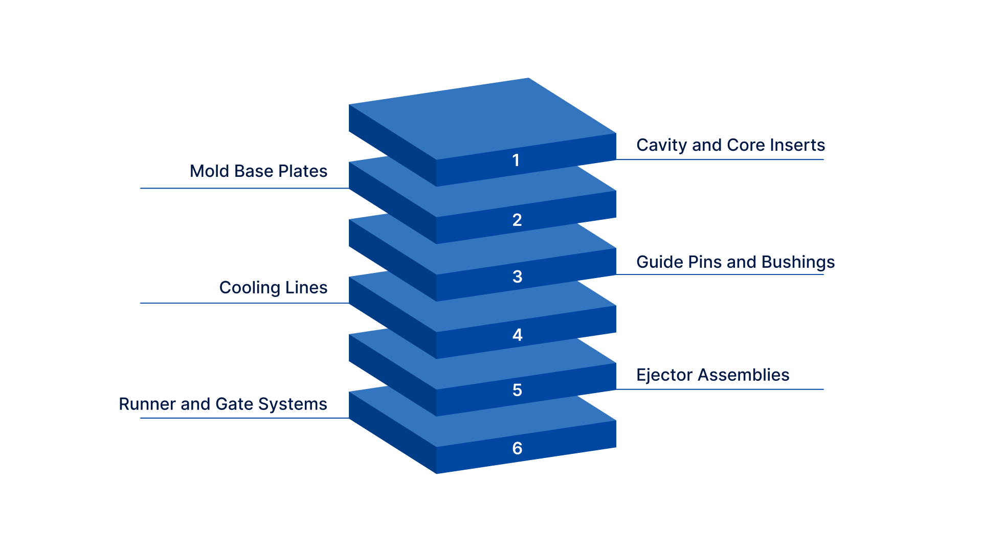
Cavity and Core Inserts: Cavity and core inserts form the external and internal geometry of the molded part. They define dimensional accuracy, surface finish, and shrink compensation. Proper machining, hardness selection, and alignment ensure repeatable part consistency.
Mold Base Plates: Mold base plates provide the structural framework that supports all mold components. They maintain alignment under clamping force, absorb injection pressure, and ensure dimensional stability throughout repeated high-tonnage molding cycles.
Guide Pins and Bushings: Guide pins and bushings control precise mold alignment during opening and closing. They prevent lateral shifting, reduce wear between mating surfaces, and protect cavity integrity under repeated mechanical cycling.
Cooling Lines: Cooling lines regulate mold temperature by circulating coolant through engineered channels. Proper placement ensures uniform heat removal, reduces thermal gradients, minimizes warpage, and stabilizes cycle time across extended production runs.
Ejector Assemblies: Ejector assemblies apply controlled mechanical force to release the molded part. Pins, sleeves, and plates must distribute force evenly to prevent part distortion, cracking, or cosmetic damage during ejection.
Runner and Gate Systems: Runner and gate systems channel molten material from the injection unit into the cavity. Their geometry controls flow rate, pressure balance, packing efficiency, and weld line formation within the mold design.
Each element must align precisely within the mold design to ensure structural stability, durability, and repeatable performance.
Beyond components, layout planning determines how the tool performs over time.
Layout Planning and Structural Architecture in Mold Design
Layout planning defines the structural logic of mold design. It determines how thermal control, material flow, mechanical force, and maintenance access work together over the tool’s lifecycle.
Layout planning and structural architecture include the following:
Cooling and Thermal Management: Effective cooling system design ensures uniform temperature control across cavities and cores. Engineers must map heat concentration zones, optimize channel spacing, and maintain turbulent flow to improve heat transfer efficiency. Proper thermal balance reduces warpage, stabilizes shrinkage, and shortens cycle time without compromising dimensional accuracy.
Runner and Gate System Architecture: Proper runner layout balances pressure and flow length between cavities. Engineers calculate runner diameter, gate type, and gate location based on material viscosity and part geometry. A well-designed runner system improves packing efficiency, reduces weld lines, and maintains consistent fill patterns across multi-cavity mold design setups.
Venting Strategy: Strategic vent placement allows trapped gases to escape during filling. Engineers determine vent depth and width based on material type and injection pressure. Effective venting prevents burn marks, short shots, and excessive internal stress while improving surface finish consistency in mold design.
Ejection System Configuration: Balanced ejector placement distributes force evenly across structural areas of the part. Engineers analyze wall thickness and rib locations to avoid deformation during release. Proper ejection system configuration protects cosmetic surfaces and reduces mechanical stress on core components.
Mold Base Selection: Proper mold base selection considers clamping force, cavity count, and projected shot volume. High-strength plates and precision-machined support pillars maintain alignment under repeated injection pressure. A rigid structural base ensures long-term dimensional stability within mold design.
Maintenance and Lifecycle Planning: Accessible inserts, replaceable wear components, and standardized hardware simplify preventive maintenance. Engineers design for disassembly, cleaning, and part replacement. Service-friendly mold design reduces downtime, lowers lifecycle costs, and extends operational reliability.
Strong layout planning enhances mold design durability and production stability.
Best Practices for Optimizing Mold Design for Long-Term Production
Even a technically sound mold design can fail without structured validation. Best practices ensure that engineering decisions translate into predictable production performance, cost control, and long-term durability.
Adopt these mold design best practices:
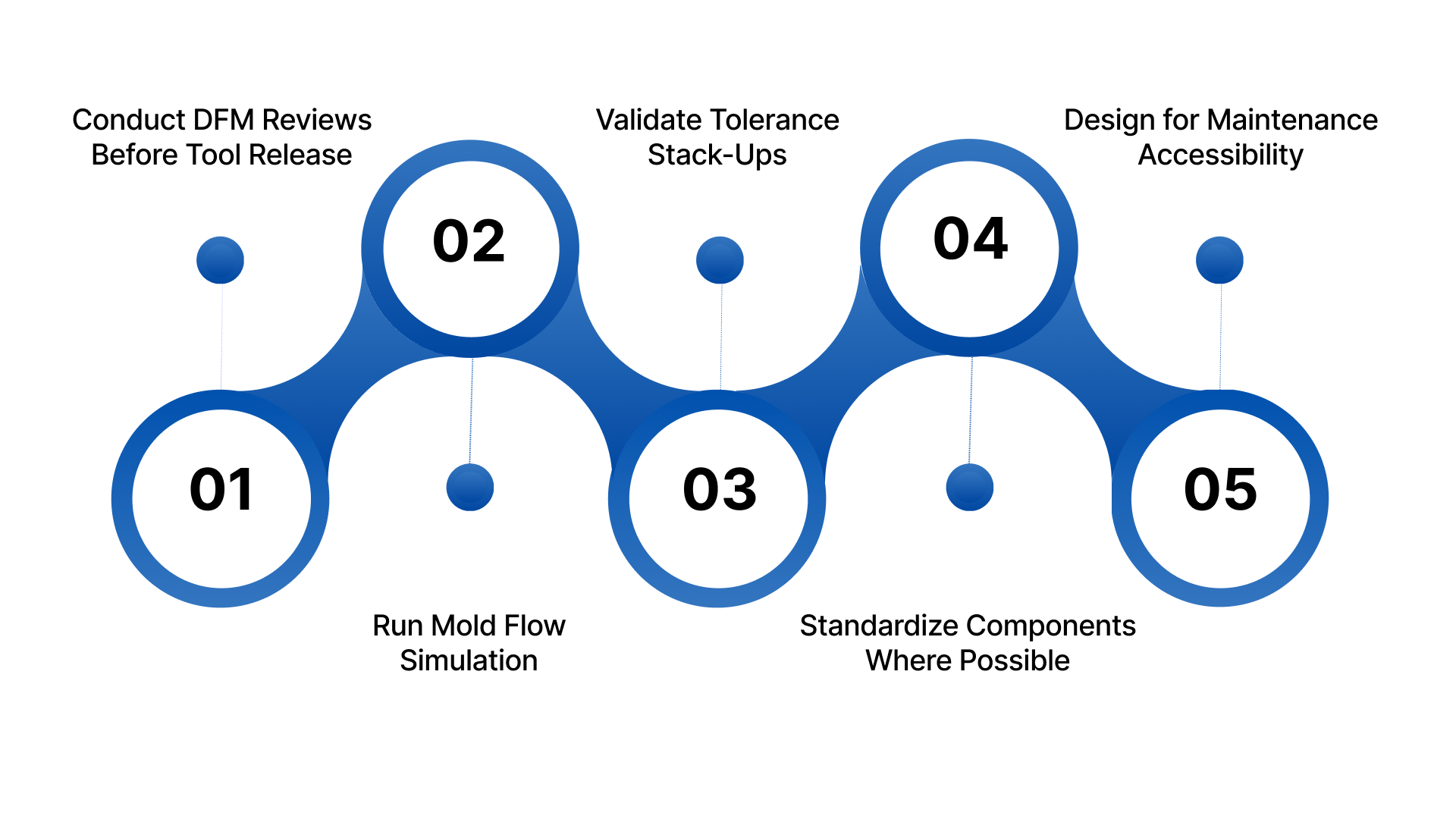
Conduct DFM Reviews Before Tool Release: Design for Manufacturability (DFM) reviews evaluate wall thickness, rib ratios, draft angles, and gating feasibility before steel cutting begins. Cross-functional teams identify risk areas early, adjust geometry if needed, and align mold design with processing capabilities to prevent costly rework.
Run Mold Flow Simulation: Mold flow analysis predicts filling patterns, pressure distribution, air traps, weld lines, and shrinkage behavior. Engineers use simulation data to optimize gate placement, cooling layout, and packing parameters. This reduces trial-and-error adjustments during sampling and improves first-shot success rates.
Validate Tolerance Stack-Ups: Tolerance stack-up analysis evaluates how dimensional variations accumulate across mating features. Engineers compare CAD tolerances with realistic molding capability to ensure functional fit. This practice protects assembly performance and ensures mold design supports consistent dimensional repeatability.
Standardize Components Where Possible: Using standardized mold bases, ejector components, and cooling fittings improves part availability and reduces custom machining. Standardization simplifies maintenance, shortens lead times, and enhances reliability by leveraging proven, field-tested mold design elements.
Design for Maintenance Accessibility: Accessible inserts, removable cores, and clearly segmented components allow quick servicing. Engineers design mold layouts to minimize disassembly time and prevent damage during maintenance. This approach reduces downtime and protects long-term mold design performance.
These strategies strengthen mold design consistency, reduce production risk, and control lifecycle costs.
However, many projects still suffer from avoidable errors.
Common Mold Design Mistakes That Increase Cost and Risk
Even experienced teams encounter preventable mold design errors. Most failures originate during early planning, not during production. Identifying these risks early protects the budget, timeline, and part quality.
Avoid these mold design failures:
Ignoring Material Shrink Rates: When engineers underestimate or generalize shrink values, parts fall out of tolerance after cooling. This leads to dimensional corrections, steel rework, and repeated sampling. To avoid this, confirm resin grade data, validate shrinkage through simulation, and apply precise compensation within the mold design.
Overcomplicating Parting Lines: Complex parting lines increase machining difficulty, sealing issues, and flash risk. They also complicate maintenance and alignment. Engineers should simplify geometry where possible, align parting surfaces with natural contours, and prioritize manufacturability during mold design development.
Poor Cooling Channel Placement: Improper cooling layout creates thermal imbalance, warpage, and longer cycle times. Hot spots accelerate tool wear and reduce dimensional consistency. Engineers must map heat zones, position channels near critical areas, and maintain uniform spacing for efficient thermal control.
Inadequate Venting: Insufficient venting traps gases during filling, causing burn marks, short shots, and internal stress. Over time, trapped gases can damage cavity surfaces. Proper vent depth calculation, strategic placement at flow ends, and periodic maintenance protect mold design performance.
Underestimating Structural Support: Weak support pillars or undersized plates allow mold deflection under clamping pressure. This leads to flash, uneven wear, and misalignment. Engineers must calculate projected area forces and select robust mold base components to maintain structural integrity.
Correcting mold design errors after tool build dramatically increases cost, lead time, and production risk.
Partnering with experienced engineers reduces these risks and strengthens mold design reliability from concept to launch.
How Evok Polymers Supports Advanced Mold Design and Manufacturing?
Evok Polymers approaches mold design as a structured, engineering-led process. We support OEMs and product developers who demand precision, repeatability, and long-term durability from their tooling investments.
We deliver:
Conduct Structured Mold Design Reviews: Analyze part geometry, material selection, tolerance zones, and production targets before tool release. Our cross-functional engineering reviews identify risk areas early, align mold design with manufacturing capability, and prevent costly post-build modifications.
Perform Mold Flow Validation: Simulate filling patterns, pressure distribution, weld lines, and shrink behavior using advanced analysis tools. We use data-driven insights to refine gate location, runner balance, and cooling layout, improving first-shot accuracy and reducing sampling iterations.
Optimize Cooling System Performance: Engineer cooling channel placement based on thermal mapping and heat concentration zones. We design for uniform heat extraction, reduced cycle time, minimized warpage, and extended tool life under high-volume production conditions.
Manufacture Precision Tooling: Machine cavities, cores, and structural components using tight-tolerance processes and quality-controlled inspection systems. Our precision manufacturing ensures mold design intent translates accurately into durable, production-ready tooling.
Plan for Lifecycle Reliability: Design molds with accessible inserts, standardized components, and maintenance-friendly architecture. We focus on long-term performance, minimizing downtime, reducing maintenance costs, and preserving dimensional consistency over millions of cycles.
Engineers choose Evok Polymers because we integrate mold design expertise with disciplined manufacturing execution. We reduce risk before steel is cut and protect production performance long-term.
Conclusion
Mastering mold design requires more than CAD modeling. It demands disciplined planning, validated engineering principles, and lifecycle thinking. Every decision in mold design affects part quality, production efficiency, and tooling cost. When teams rush mold design or overlook simulation and thermal balance, they face expensive rework and delayed launches.
If your tooling investment must deliver precision and repeatability, your mold design strategy cannot rely on assumptions.
Are you confident your current mold design approach eliminates risk before manufacturing begins?
Evok Polymers helps manufacturers strengthen mold design from concept through tool build. Request a quote today to evaluate your mold design strategy, reduce tooling risk, and ensure long-term production success.
Frequently Asked Questions
1. What is mold design in injection molding?
Mold design is the engineering process of creating a tool that shapes molten material into a finished part. It defines cavity geometry, cooling layout, runner systems, venting, and ejection methods. Proper mold design ensures dimensional accuracy, repeatability, efficient cycle time, and long-term tool durability in production.
2. Why is mold design important for product quality?
Mold design directly affects part dimensions, surface finish, structural strength, and defect control. Poor mold design can cause warpage, sink marks, flash, and inconsistent shrinkage. A well-engineered mold design ensures uniform filling, balanced cooling, and controlled ejection, resulting in stable, repeatable manufacturing performance.
3. How long does mold design take?
Mold design timelines depend on part complexity, cavity count, and validation requirements. Simple mold design projects may take a few weeks, while complex, multi-cavity or high-precision tools require detailed simulation, engineering review, and optimization, extending the design phase before manufacturing begins.
4. What software is used for mold design?
Engineers use CAD platforms such as SolidWorks, NX, and Creo for 3D mold design development. Mold flow simulation software like Autodesk Moldflow predicts filling patterns, shrinkage, and cooling behavior. These tools improve design accuracy and reduce costly modifications during sampling and production.
5. How can mold design reduce production costs?
Effective mold design lowers scrap rates, shortens cycle time, and minimizes maintenance downtime. By optimizing cooling channels, runner balance, and structural support, manufacturers improve efficiency and extend tool life. Strong mold design reduces rework, protects part quality, and ensures predictable long-term production performance.