Have you ever seen an insert-molded part fail under load because the insert loosened, cracked the housing, or pulled out entirely?
Structural failure is more common and more costly than many engineers expect.
According to the U.S. Consumer Product Safety Commission (CPSC), more than 300 product recalls occur each year under its jurisdiction, and consumer product-related incidents cost the U.S. over $1 trillion annually in deaths, injuries, and property damage. Many of these failures trace back to design and manufacturing defects.
In insert molding, weak retention geometry, thermal mismatch, and poor process control often compromise structural integrity. The solution lies in engineering-driven design, validated tooling strategies, and tightly controlled molding parameters.
In this insert molding design guide, you will learn how to improve structural performance, reduce failure risks, and transition confidently from prototype to production.
Key Takeaways
Structural integrity starts at the insert interface. Mechanical retention geometry determines whether loads transfer safely or cause long-term pull-out failure.
Thermal expansion mismatch is a hidden risk factor. Ignoring CTE differences between metal and plastic creates internal stress that weakens durability.
Uniform wall design protects high-load zones. Consistent thickness around inserts prevents stress concentration and crack initiation.
Process control directly impacts bond strength. Melt temperature, pressure, and cooling conditions influence encapsulation quality and repeatability.
Simulation reduces structural guesswork. Mold flow and stress analysis identify weak points before tooling investment, saving time and cost.
What Is Insert Molding and Why Structural Integrity Matters?
Insert molding bonds a pre-formed insert, typically metal, into a plastic component during injection molding. It allows lighter assemblies, fewer parts, and stronger mechanical performance.
However, structural integrity depends on:
Effective load transfer between insert and resin: The interface between insert and plastic must distribute applied forces evenly. Poor bonding or weak mechanical interlock concentrates stress and increases the risk of cracking or separation.
Resistance to pull-out and shear forces: The insert geometry must withstand axial and lateral loads during real-world use. Knurls, grooves, and undercuts improve mechanical locking and prevent loosening under vibration or cyclic stress.
Thermal expansion compatibility: Metal and plastic expand at different rates under temperature changes. If not engineered correctly, this mismatch creates internal stress, leading to microcracks, warping, or long-term bond failure.
Stress distribution under operational loads: Uniform wall thickness and proper insert positioning prevent stress concentration. Sharp transitions or thin sections near inserts amplify load intensity and weaken the surrounding plastic structure.
Insert stability during the molding process: If the insert shifts, floats, or tilts during injection, it compromises alignment and bonding. Secure fixturing and balanced cavity pressure are critical to maintaining dimensional and structural consistency.
Without proper design, inserts loosen, crack the surrounding plastic, or shift during molding.
Key Principles of Insert Molding Design
Structural integrity begins with disciplined engineering decisions. Every feature, material, and mold element affects long-term durability.
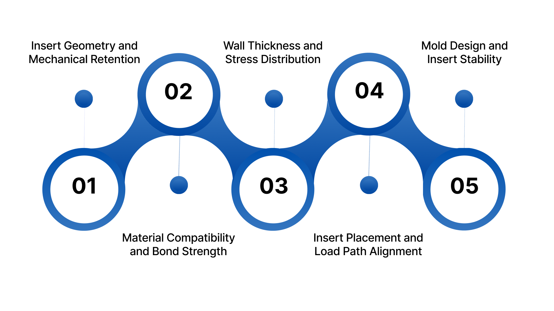
Below are five critical principles, from insert geometry to mold design:
1. Insert Geometry and Mechanical Retention
Insert shape directly impacts pull-out resistance.
Increase surface contact area.
Design for shear load resistance.
Avoid smooth cylindrical surfaces.
Use knurls, grooves, and undercuts.
Align insert features with the load direction.
Strong mechanical interlocking prevents bond failure under cyclic stress.
2. Material Compatibility and Bond Strength
Material mismatch creates stress.
Validate chemical compatibility.
Evaluate adhesion characteristics.
Match thermal expansion coefficients.
Consider corrosion between metal and resin.
Use glass-filled resins where structural strength matters.
Balanced material pairing improves long-term performance.
3. Wall Thickness and Stress Distribution
Non-uniform walls create stress concentrations.
Use ribs strategically.
Reinforce high-load zones.
Prevent sink around insert areas.
Avoid abrupt thickness transitions.
Maintain consistent wall thickness.
Uniform material flow reduces crack risk.
4. Insert Placement and Load Path Alignment
Placement defines performance.
Maintain proper edge distance.
Evaluate torsional stress paths.
Center inserts when possible.
Avoid positioning near thin walls.
Align the insert axis with the primary load.
Correct alignment ensures predictable load transfer.
5. Mold Design and Insert Stability
Mold design controls insert movement.
Balance cavity pressure.
Prevent insert float or tilt.
Optimize gating around inserts
Design controlled cooling paths.
Use secure insert locating features.
Mold stability directly affects structural consistency.
Material Selection for Structural Performance
Material pairing determines structural durability.
Focus on:
Corrosion-resistant inserts
High tensile strength resins
Long-term creep resistance
Glass or mineral reinforcement
Heat-resistant polymers for thermal cycling
Always validate performance under simulated load conditions before tooling release.
Material selection influences plastic flow, which directly impacts encapsulation quality.
Wall Thickness, Encapsulation & Plastic Flow
Encapsulation ensures secure bonding.
Key design considerations:
Avoid voids and air traps.
Ensure full insert coverage.
Design proper gate placement.
Analyze flow using mold simulation.
Maintain adequate packing pressure.
Proper flow prevents weak bonding zones.
However, even a strong design fails if tolerances and thermal behavior are ignored.
Tolerances, Thermal Expansion & Structural Fit
Thermal mismatch generates internal stress.
Engineers must:
Allow tolerance compensation.
Validate dimensional stack-ups.
Design clearance where needed.
Prevent over-constraint of inserts.
Calculate coefficient of thermal expansion differences.
Precision fit prevents cracking during cooling and operation.
Beyond design, process parameters heavily influence structural results.
Process Parameters That Affect Structural Integrity
Even a perfect design fails under poor processing.
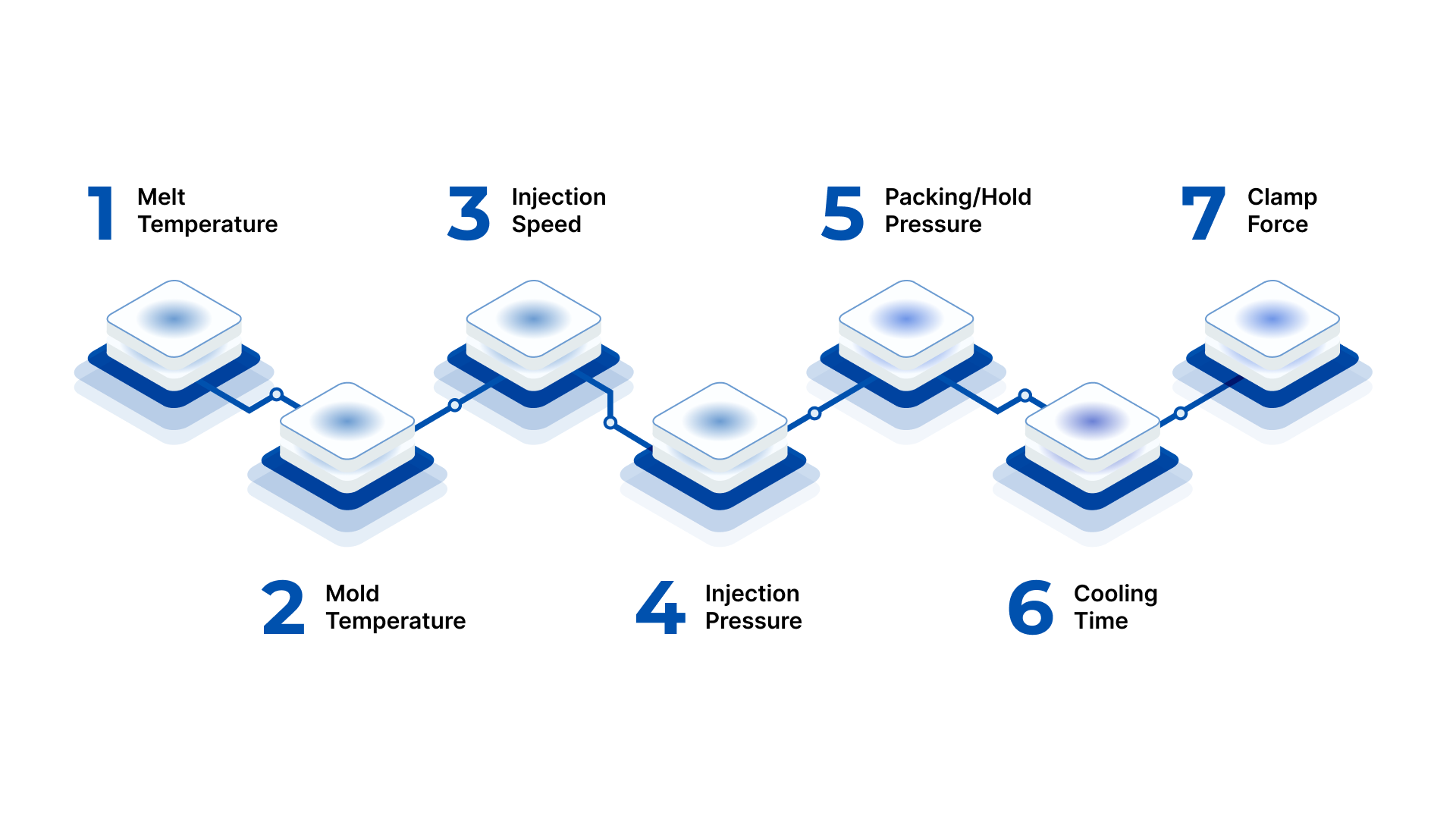
Control these seven parameters:
Melt Temperature: Affects bonding and resin flow.
If the melt temperature is too low, the resin will not properly wet the insert surface, weakening adhesion. If too high, it can degrade material properties and increase residual stress.
Mold Temperature: Influences crystallinity and stress levels.
Proper mold temperature ensures controlled cooling and uniform crystallization in semi-crystalline resins. Incorrect temperatures create uneven shrinkage, internal stress, and potential cracking around inserts.
Injection Speed: Impacts insert displacement risk.
Excessive injection speed can shift or tilt inserts due to sudden pressure impact. Controlled speed ensures gradual cavity filling and maintains insert positioning accuracy.
Injection Pressure: Determines cavity fill and bonding strength.
Adequate pressure ensures complete encapsulation around insert features. Insufficient pressure causes short shots or weak bonding, while excessive pressure increases stress concentration.
Packing/Hold Pressure: Reduces voids around inserts.
Proper packing compensates for material shrinkage during cooling. Without sufficient hold pressure, voids or sink marks may form near inserts, reducing structural reliability.
Cooling Time: Controls shrinkage and internal stress.
Allowing sufficient cooling stabilizes part geometry before ejection. Premature ejection can cause warpage, stress buildup, or microcracks near insert interfaces.
Clamp Force: Maintains cavity stability during injection.
Correct clamp force prevents mold separation under high injection pressure. Insufficient force causes flash and dimensional variation, affecting insert alignment and structural consistency.
Stable processing ensures repeatable structural performance.
Even so, many failures stem from avoidable design errors.
Common Design Mistakes That Compromise Strength
Even with strong materials and advanced tooling, structural failure often begins at the design stage. Small oversights in insert placement, geometry, or material pairing can create stress concentrations and weak bonding zones. Identifying and correcting these mistakes early prevents costly rework and field failures.
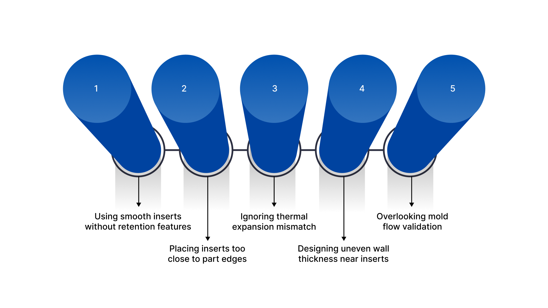
Avoid these 5 critical mistakes:
Using smooth inserts without retention features
Smooth inserts rely primarily on surface adhesion, which weakens under vibration, cyclic loading, or thermal expansion. This increases the risk of pull-out or rotation over time.
Incorporate knurls, grooves, undercuts, or through-holes to create mechanical interlocking and improve long-term retention strength.
Placing inserts too close to part edges
When inserts sit near thin walls or edges, the surrounding plastic lacks sufficient material to distribute stress. This often leads to cracking or edge splitting under load.
Maintain adequate edge distance and reinforce surrounding walls to ensure proper load distribution and structural support.
Ignoring thermal expansion mismatch
Metals and plastics expand at different rates during heating and cooling. If not accounted for, this mismatch generates internal stress that weakens the insert-plastic interface.
Select compatible materials, allow tolerance compensation, and validate thermal behavior during design simulation.
Designing uneven wall thickness near inserts
Abrupt wall transitions create stress concentrations and uneven cooling, increasing the risk of warpage or sink marks around inserts.
Maintain uniform wall thickness and use gradual transitions or ribs to reinforce high-load zones without creating shrinkage issues.
Overlooking mold flow validation: Poor flow design can create weld lines, voids, or incomplete encapsulation near inserts, weakening structural performance.
Conduct mold flow analysis to optimize gate location, pressure distribution, and encapsulation quality before final tooling.
Correcting these errors significantly improves durability.
Before releasing tooling, use a structured checklist.
Insert Molding Design Checklist for Engineers
Before releasing tooling or moving into production, conduct a structured engineering review. A formal checklist ensures that structural integrity is validated not only in theory, but also in manufacturability and repeatability. Each item below should be verified through calculations, simulations, and cross-functional review.
Review these 5 essentials:
Verified insert retention geometry: Check that inserts include knurls, grooves, undercuts, or through-features designed for mechanical interlocking.
Verify pull-out resistance against expected axial and torsional loads.
Confirm alignment of retention features with the primary load direction to prevent rotational or shear failure.
Validated material compatibility: Confirm compatibility between insert and resin, including adhesion behavior and corrosion resistance.
Compare coefficients of thermal expansion to assess stress risk during cooling and service temperature changes.
Evaluate tensile strength, creep resistance, and environmental durability for long-term structural performance.
Uniform wall thickness around inserts: Inspect CAD models for abrupt thickness transitions near inserts.
Ensure adequate material surrounds the insert to distribute the load evenly.
Check for sink risk, warpage potential, and stress concentration areas that may reduce mechanical strength.
Simulated mold flow and stress analysis: Run mold flow analysis to verify complete encapsulation and eliminate air traps.
Evaluate weld line locations to ensure they do not fall in high-load zones.
Conduct a structural simulation to assess stress distribution and deformation under real operating conditions.
Process window established for repeatability: Define acceptable ranges for melt temperature, injection pressure, and cooling time.
Confirm that the process window maintains insert position and bonding integrity.
Validate repeatability through pilot runs before scaling to full production.
A structured review reduces costly tooling rework and prevents structural failures in the field.
To ensure these principles translate into production success, partner with experienced manufacturers.
How Evok Polymers Supports Structural Insert Molding Design?
Evok Polymers is a precision injection molding partner specializing in structurally demanding insert-molded components. We work with OEMs, product design engineers, and manufacturers in industries where mechanical strength, dimensional accuracy, and long-term durability are critical.
Whether you are developing load-bearing housings, threaded metal insert components, or hybrid assemblies, we focus on engineering validation before production.
Here’s how Evok Polymers delivers engineering-driven solutions for structural insert molding:
Detailed DFM analysis focused on load paths: We evaluate part geometry, insert placement, and stress zones to ensure proper load transfer and eliminate weak structural areas before tooling.
Material selection guidance for structural durability: We help select compatible resin and insert combinations based on strength, thermal expansion behavior, and long-term environmental performance.
Precision tooling with secure insert positioning: Our tooling solutions incorporate reliable insert fixturing and cavity balance to prevent shift, tilt, or displacement during injection.
Mold flow simulation for encapsulation validation: Evok Polymers performs simulation analysis to confirm complete insert encapsulation, eliminate voids, and optimize gate placement for structural integrity.
Controlled production processes for repeatability: We establish validated process windows and maintain strict quality control to ensure consistent bonding strength across production volumes.
Engineers prefer Evok Polymers because we approach insert molding as an engineering challenge, not just a molding operation. We prioritize structural performance, risk reduction, and production stability. Our team collaborates early, identifies failure risks proactively, and delivers components that meet real-world mechanical demands.
Conclusion
Structural integrity in insert molding design does not happen by chance. It results from deliberate geometry design, compatible materials, controlled tolerances, and tightly managed process parameters.
When engineers overlook retention features, thermal expansion, or mold stability, failures surface under load, during thermal cycling, or after long-term use.
If your insert-molded components must withstand mechanical stress, vibration, or environmental exposure, you need more than basic molding expertise. You need engineering validation built into every step.
Are you confident your current insert molding design can withstand real-world structural demands?
Evok Polymers helps manufacturers design and produce structurally reliable insert-molded components. Request a quote today to evaluate your design, reduce risk, and ensure long-term performance.
Frequently Asked Questions
1. What is the purpose of insert molding?
Insert molding combines metal or other inserts with plastic during injection molding to create a single integrated component. It improves structural strength, reduces assembly steps, enhances electrical or mechanical performance, and lowers overall production costs by eliminating secondary fastening or bonding operations.
2. How do you increase the strength of insert-molded parts?
Increase strength by designing mechanical retention features like knurls or undercuts, maintaining uniform wall thickness, selecting compatible materials, and controlling molding parameters. Conduct mold flow and stress simulations to ensure proper encapsulation and balanced load distribution across the insert interface.
3. What materials are commonly used in insert molding?
Common insert materials include brass, stainless steel, aluminum, and copper alloys. Frequently used plastics include nylon (PA), PBT, ABS, polypropylene, and glass-filled engineering resins. Material selection depends on load requirements, thermal exposure, environmental conditions, and long-term durability needs.
4. What causes insert pull-out failure?
Insert pull-out occurs due to smooth insert surfaces, insufficient mechanical retention, poor bonding, uneven wall thickness, or thermal expansion mismatch. Excessive vibration, cyclic loading, or improper molding parameters can also weaken the insert-to-plastic interface over time.
5. How does thermal expansion affect insert molding?
Metals and plastics expand at different rates when exposed to temperature changes. This mismatch can create internal stress, microcracks, or bond separation. Engineers must evaluate thermal expansion coefficients and allow proper tolerance compensation during the design phase.