Introduction
Parting lines are unavoidable in injection molding, but their placement determines whether your product looks premium or poorly manufactured. A parting line on a smooth, visible surface creates an obvious seam that detracts from appeal, while one strategically hidden along an edge becomes virtually invisible.
Many designers struggle with this challenge because they don't consider parting lines until after mold design begins. This timing leads to costly revisions, compromised aesthetics, and unexpected quality issues.
According to ISO 20457 standards, the parting line is the unavoidable seam where mold halves separate. It cannot be eliminated, but it can be strategically managed. You'll learn how to plan parting lines for optimal aesthetics, functionality, and manufacturing cost.
TLDR: Key Takeaways
- A parting line is the visible seam where two mold halves meet—it's inevitable but manageable through strategic design
- Placement affects part aesthetics, structural integrity, manufacturing cost, and production efficiency
- Straight parting lines reduce tooling costs while complex curves improve aesthetics but increase expense
- Early collaboration with your mold manufacturer prevents costly revisions
What is a Parting Line in Injection Molding?
A parting line is the line or surface where the two halves of an injection mold (A-side and B-side) meet to form the mold cavity.
This meeting point is fundamental to injection molding because the mold must separate to eject the finished part.
What parting lines look like on finished parts:
- Typically a faint raised ridge, depression, or texture change along the seam
- Sometimes accompanied by flash (thin excess material squeezed between mold halves)
- Appearance ranges from nearly invisible (when placed on sharp edges) to obvious (when placed on smooth curved surfaces)
Relationship with other mold features:
The parting line location drives several interconnected mold design decisions:
- Draft angles: Must angle away from the parting line to allow part ejection
- Gate placement: Often positioned near the parting line to optimize material flow
- Ejector pins: Typically push from the B-side of the mold
- Surface quality: Strategic placement prevents visible marks on critical surfaces
During mold design, Evok Polymers coordinates these elements to avoid ejector pins on visible surfaces while optimizing gate locations to prevent flow marks and burn marks.
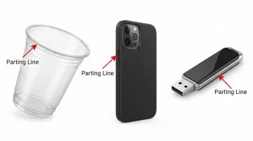
Simple examples:
- A plastic cup has its parting line along the outer brim edge
- A smartphone case typically has a parting line running around its perimeter at the midpoint
- A USB drive shows a visible parting line where the mold segments met
Types of Parting Lines
Straight Parting Lines
Straight parting lines are the simplest and most cost-effective option, where the mold separates along a single flat plane. This geometry minimizes mold complexity compared to stepped or curved alternatives, making it the easiest to machine and maintain.
When to use straight parting lines:
- Parts with relatively simple geometry that can be divided cleanly into two halves
- Designs without undercuts requiring side actions
- Budget-conscious projects where tooling cost is a primary concern
Key advantages:
- Lowest tooling cost—simple flat geometry requires minimal CNC machining time
- Easiest to maintain over the mold's lifetime
- Fastest production cycles with predictable part quality
- Most reliable mold alignment and minimal flash risk
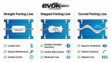
Stepped Parting Lines
Stepped parting lines have multiple levels or steps where the mold halves meet, creating a stair-step pattern rather than a single plane.
This design allows more complex part geometries to be molded without requiring expensive side actions or lifters, reducing overall mold complexity.
Purpose and applications:
Stepped parting lines handle parts with features at different heights or depths that would otherwise require more complex mold mechanisms.
Common uses include:
- Parts with features at multiple elevations on the same side
- Designs where lateral forces during molding could cause mold shift
- Applications requiring wedge-shaped inserts for stability
- Geometries that would otherwise need costly side actions
Curved and Irregular Parting Lines
Curved parting lines follow a non-linear path around the part, often used to hide the seam or accommodate complex organic shapes. The design intent is strategic: curved parting lines can follow natural contours, texture transitions, or decorative elements where they'll be less visible.
Trade-offs to consider:
- Increased mold complexity and cost due to precise multi-axis CNC milling requirements
- Longer machining time and meticulous hand-finishing (benching) to ensure perfect mating
- Potentially more difficult mold maintenance over time
- Superior aesthetics for consumer-facing products where appearance is critical
Complex contoured parting lines require highly precise machining, adding both time and expense to the tool-making process—but for premium consumer products, this investment improves perceived quality.
Angled Parting Lines
Angled parting lines separate along a plane that is not perpendicular to the direction of mold opening, requiring careful draft angle consideration. This approach is necessary when parts have features that must be oriented at specific angles or when optimizing material flow and minimizing weld lines.
Challenges:
- Requires precise draft angle calculation to ensure successful ejection
- May complicate the ejection process compared to straight parting lines
- Typically increases tooling cost due to added complexity
Design Considerations for Parting Line Placement
Strategic parting line placement balances aesthetics, function, and cost. The "gold standard" is placing the parting line along a sharp edge, which camouflages the seam and avoids the need for tight tolerances on smooth surfaces.
Aesthetic priorities:
- Place parting lines where they'll be least visible in typical use—bottom surfaces, inside corners, along existing design lines
- Position seams at texture transitions where material changes naturally disguise the line
- Avoid smooth, continuously curved surfaces where any mismatch creates a noticeable step
Functional considerations:
- Never place parting lines across critical sealing surfaces (like O-ring grooves)—any imperfection creates a leak path
- Avoid placing lines on mating features or areas requiring tight tolerances, as the seam affects dimensional accuracy
- Keep parting lines away from high-stress areas where they could create stress concentration points
Draft and Wall Thickness Optimization
Draft angle relationship:
Parting line placement determines the direction of draft. Features must have adequate draft perpendicular to the parting line for successful ejection.
When designing parts with textured surfaces, add one degree of additional draft for every 0.001 inch of texture depth to aid ejection.
Wall thickness uniformity:
Locate parting lines to maintain consistent wall thickness on both sides when possible, minimizing sink marks and warpage. During the molding trial phase, Evok Polymers makes wall thickness modifications to minimize sink and optimize part quality.
Mold Complexity and Cost Impact
Mold complexity and cost:
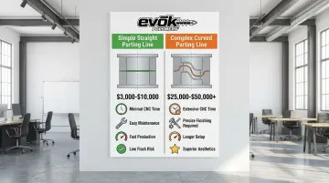
Simpler parting line geometry (straight vs. curved, single plane vs. stepped) directly reduces tooling cost and lead time.
A case study comparing mold costs found that a $12,000 "cheap" overseas mold resulted in over $49,500 in total costs due to repairs and delays, while a $49,000 domestic production mold performed reliably—demonstrating that parting line precision matters.
Coordination with gates and ejector pins:
Gates are often placed near the parting line for optimal material flow. Ejector pins typically push from the B-side, so parting line placement affects ejection strategy.
The optimal approach involves analyzing the part model to determine ejector pin placement while avoiding locations that would compromise visual surfaces.
Impact of Parting Lines on Part Quality and Cost
Aesthetic Impact
Parting lines create visible effects that can detract from premium appearance, especially on high-gloss or consumer-facing surfaces.
The seam appears as a raised ridge, depression, or texture change. On smooth surfaces, any mismatch between mold halves becomes obvious and feels rough to the touch.
Flash (thin excess material squeezed between mold halves) forms along parting lines when plastic pressure exceeds clamp force. This defect may require secondary finishing operations like manual trimming, sanding, or polishing, increasing cost per unit and slowing production.
Functional and Structural Impact
Parting lines can create stress concentration points where the two mold halves meet, potentially weakening the part if placed in high-stress areas. Dimensions measured across a parting line cannot be held to the same precision as features not bisected by the mold halves—mismatch must be accounted for in tolerance stacks.
Design considerations for specific features:
- Light pipes: Never place parting lines on the circumference to avoid light leakage
- Cylinders: Must be line of draw and slightly drafted for proper function
- Critical dimensions: Avoid splitting precision features across the parting line
Cost Implications
Tooling costs:
- Simple straight parting lines are most economical
- Curved or stepped lines increase CNC machining time significantly
- Contoured parting lines require precise multi-axis milling and careful hand-finishing
- Complex geometries add both tooling time and expense
Production costs:
- Post-molding deflashing adds secondary operations and labor
- Flash removal may require manual trimming or finishing
- Higher scrap rates when flash and mismatch exceed tolerances
- Quality issues can slow production throughput
Evok Polymers' approach:
With 25+ years of experience, Evok's team is upfront about cost implications of different parting line strategies. They help customers make informed decisions that balance aesthetics with budget during the design phase. Their process includes dedicated "Match Mate Parting Line Adjustments" to ensure precision alignment and minimize flash in final molded parts.
Best Practices for Parting Line Design
Optimizing parting line placement requires balancing aesthetics, manufacturability, and cost. These strategies help you achieve the best results:
Strategic Placement Techniques
Position along natural design breaks:
- Place parting lines on sharp edges, texture transitions, or surfaces facing away from users
- Hide seams along existing product features like ribs, logos, or decorative elements
- The gold standard: positioning on a sharp edge where the line becomes virtually invisible
Incorporate concealment features:
- Add slight recesses or chamfers at intended parting line locations
- Use texture strategically to disguise imperfections (add 1° draft per 0.001" texture depth)
- Design in natural break lines that align with aesthetic elements
Design Process Best Practices
Involve your manufacturer early. Evaluate parting line options during the CAD modeling phase, before finalizing the design. Industrial design teams can conduct pre-molding reviews that identify optimal placement and prevent costly tooling changes.
Run a comparative parting line study. For complex parts, analyze 2-3 placement options with your manufacturer. Consider trade-offs between aesthetics, function, and cost before cutting steel.
Material-Specific Considerations
Thermoplastics offer more forgiving tolerances and easier flash removal, giving you flexibility in parting line placement.
Liquid Silicone Rubber (LSR) demands exceptional precision. LSR can flash in gaps as small as 0.0002 inches (5 microns), requiring tighter tolerances and simplified parting line strategies compared to thermoplastics.
Common Parting Line Issues and Solutions
Excessive Flash Problems
Flash occurs when worn mold surfaces, insufficient clamp tonnage, or mold misalignment allow material to escape at the parting line.
Ensuring sufficient clamp pressure is the primary preventive measure—if plastic pressure exceeds clamp force, flash is inevitable.
Solutions:
- Verify clamp tonnage meets projected area requirements
- Implement proper mold maintenance and repair worn parting surfaces
- Optimize process parameters to reduce injection pressure without causing short shots
- Ensure vents are within recommended depths (typically <0.0015 inch for semi-crystalline resins)
Parting Line Shift or Mismatch
When the two mold halves don't align perfectly, a step forms at the parting line.
Pressure-sensitive paper can reveal uneven clamp pressure at the parting line, distinguishing between mold and clamp alignment issues.
Prevention:
- Precision mold making with proper guide pin design
- Regular mold inspection and maintenance
- Adjust platen alignment and ensure mold components aren't worn
- Use recommended clamp pressure range (7,000 to 18,000 psi for troubleshooting)
Sink Marks Near Parting Lines
Wall thickness variations across the parting line cause sink marks as thicker sections cool unevenly. This becomes especially problematic when designers don't account for how parting line placement affects material flow and cooling.
Prevention:
- Maintain uniform wall thickness across the parting line (typically within 25% variation)
- Adjust cooling strategy to compensate for necessary thickness transitions
- Modify wall thickness during mold trials to minimize visible sink
- Position parting line to avoid areas where cosmetic appearance is critical
Frequently Asked Questions
What is a parting line?
A parting line is the visible seam on an injection-molded part where the two halves of the mold meet and separate to allow part ejection. It appears as a faint ridge, depression, or texture change along the interface between the core and cavity.
What is the difference between parting line and flash?
The parting line is the designed meeting point between mold halves, while flash is unwanted thin excess material that squeezes out along the parting line during molding. Flash occurs due to mold wear, improper clamping pressure, or excessive injection pressure.
How much does a plastic injection mold cost?
Mold costs range from $3,000-$10,000 for simple designs with straight parting lines to over $50,000 for complex geometries with intricate parting lines. Early design optimization significantly reduces tooling costs and avoids expensive rework.
Where should the parting line be placed on my part?
Place parting lines on non-visible surfaces, natural design breaks, or areas away from critical dimensions and sealing surfaces. Work with your mold manufacturer during the design phase to balance aesthetics, function, and cost.
Can parting lines be eliminated completely?
Parting lines cannot be eliminated entirely because the mold must separate to eject the part. However, their visibility can be minimized through strategic placement on sharp edges, proper mold design with precision alignment, and post-molding finishing operations if necessary.
How do parting lines affect part strength?
Parting lines can create minor stress concentration points, so place them away from high-stress areas. Properly designed parting lines with minimal flash and good mold alignment have negligible impact on part strength.
Ready to optimize your parting line design? Contact Evok Polymers at 612-991-2001 to discuss your project. Our industrial designers conduct comprehensive pre-molding design reviews to reduce risk and optimize both quality and cost.