Introduction
Picture this: A product designer submits their first injection mold order and eagerly awaits the samples. When parts arrive, there's warping along the edges, sink marks on cosmetic surfaces, and components stuck in the mold cavity. The diagnosis? Design features that clash with the physics of injection molding. All of it preventable with an upfront Design for Manufacturability (DFM) review.
According to NASA technical research, fixing a design error after tooling has been cut costs approximately 10× more than correcting it during the design phase — and up to 100× more if caught during production. Tooling modifications drain budgets, stall product launches, and hand market timing to competitors who got their DFM right the first time.
TLDR:
- DFM optimizes part geometry for efficient, defect-free injection molding before tooling begins
- Skipping DFM leads to 10-100× cost increases for corrections discovered after mold fabrication
- Flash, sink marks, short shots, warpage, and weld lines account for 91% of injection molding quality issues
- Proper DFM reduces cycle time by 12%, material costs by 25%, and prevents multi-week production delays
- Core DFM elements: uniform wall thickness, draft angles, rib geometry, gate placement, and undercut reduction
What Is DFM in Injection Molding?
Design for Manufacturability (DFM) is the engineering discipline that optimizes a plastic part's geometry so it can be efficiently and consistently produced through injection molding. Rather than designing purely for function or aesthetics and hoping the part can be manufactured, DFM intentionally balances performance, cosmetics, and cost from the earliest design phase.
In injection molding specifically, DFM matters because the process involves complex interactions between part geometry, material flow behavior, mold mechanics, and thermal dynamics. Small design choices create outsized effects on tooling cost, cycle time, and part quality:
- A wall section 0.5mm too thick can double cooling time
- A missing 1° draft angle causes parts to stick in the mold, halting production
- A poorly placed gate creates weak weld lines that compromise structural integrity
DFM is an ongoing review process, not a one-time sign-off. Ideally, it begins before CAD is finalized and certainly before any tooling is ordered. The earlier DFM is applied, the less costly corrections become. At EVOK, DFM analysis using Autodesk Moldflow Insight simulation begins during the quoting phase — identifying design improvements before steel is cut.
Why DFM Matters: The Cost of Skipping It
The Exponential Cost of Change
Manufacturing follows a brutal economic principle: the cost to fix a defect increases by roughly 10× at each subsequent phase of the product life cycle. Research quantifies this escalation precisely. If fixing a requirement error during the concept phase costs 1 unit, that same fix costs 3–8 units during design, 7–16 units during manufacturing, and 21–78 units during integration and testing.
In injection molding, this curve steepens dramatically once tooling begins. Steel molds represent significant capital investment—$10,000 to $50,000 or more depending on complexity. Once a mold is machined, modifications require expensive EDM (Electrical Discharge Machining), welding, or complete re-fabrication.
A medical device manufacturer learned this firsthand: attempting to save money with a $12,000 "budget" mold ultimately cost over $49,500 in rework, shipping, and emergency fixes—exceeding the $49,000 cost of the quality US-built tool they should have ordered initially.
Preventing Defects Before Production
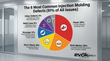
Six specific defects account for 91% of all injection molding quality issues:
- Flash (35%): Excess material at parting lines caused by mold wear or excessive pressure
- Sink marks (25%): Surface depressions over thick sections due to uneven cooling
- Short shots (18%): Incomplete cavity filling from inadequate flow or venting
- Warpage (12%): Post-mold distortion from differential shrinkage and cooling
- Weld lines (8%): Weak seams where flow fronts meet, reducing strength by 50-60% in fiber-filled materials
- Other defects (3%): Burns, voids, flow marks, and dimensional variations
The critical insight: these defects are largely preventable through proper DFM review. Sink marks result from rib thickness exceeding 60% of the nominal wall. Short shots stem from walls too thin for material flow. Warpage traces back to non-uniform wall thickness creating uneven cooling rates. Catching these issues in the design phase—when they cost pennies to fix—avoids costly scrap and rework during production runs.
Cycle Time and Tooling Longevity
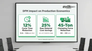
DFM directly impacts production economics. Cooling time accounts for **50–80% of the total injection molding cycle**. Since thicker walls require exponentially longer cooling, minimizing and standardizing wall thickness delivers immediate payback. A Moldex3D case study documented quantified benefits:
- 12% cycle time reduction (from 14.3 to 12.6 seconds per shot)
- 25% raw material cost savings through optimized geometry
- 45-ton reduction in clamping force (from 383 to 338 tons), lowering energy consumption
DFM also extends tooling longevity. Molds designed with proper draft angles and robust shut-offs experience less wear, and parts that eject cleanly reduce mechanical stress on ejector pins and core components. Designs that force parts to drag during ejection, by contrast, accelerate parting line wear and require frequent refurbishment.
Speed-to-Market Impact
Product redesigns due to tooling deficiencies can delay production by 4 to 6 weeks or longer. When a mold requires rework because parts won't fill, won't eject, or fail quality standards, the project halts while the tool is removed, machined, validated, and shipped back. These delays cascade through launch timelines, missing market windows and allowing competitors to capture early sales.
Companies that invest in DFM upfront avoid iterative tooling rework cycles entirely. The process forces alignment on design requirements and manufacturing constraints before teams commit to tooling—so the first mold built is the right one.
The 5 Core Principles of DFM
Principle 1: Simplify the Design
Reduce geometric complexity wherever possible. Fewer features, undercuts, and side actions translate directly to simpler molds, lower tooling cost, and fewer failure points. Every additional complexity adds mechanisms, increases machining time, and introduces potential defect sources. Challenge every feature: does this undercut add functional value worth the 50%+ tooling premium it will require?
Principle 2: Standardize Features
Use standard wall thicknesses, radii, and draft angles consistent with material and mold requirements rather than custom geometry demanding special tooling accommodations. Material suppliers publish design guidelines that reflect decades of accumulated process knowledge. Designing within these windows ensures predictable flow, consistent cooling, and reliable ejection.
Principle 3: Design for Material Behavior
Select and design around the specific shrink rate, flow characteristics, and thermal properties of the chosen resin. Polypropylene shrinks 1.0–3.0%, while ABS shrinks only 0.4–0.8%—a 4× difference that directly impacts dimensional tolerances and tooling compensation.
Different materials demand different design rules. High-flow materials like nylon can fill thin walls that would cause short shots in polycarbonate.
Principle 4: Minimize Secondary Operations
Design parts to come out of the mold ready to use or assemble. Every post-mold operation adds cost and cycle time—common examples include:
Design parts to come out of the mold ready to use or assemble. Every post-mold operation adds cost and cycle time. Common examples include:
- Trimming flash or sprues
- Drilling or tapping holes
- Inserting hardware (threaded inserts, fasteners)
- Applying secondary finishes or coatings
Strategic use of molded-in features like snap-fits, living hinges, and integrated threads eliminates these steps and reduces total part cost—even if the mold itself is slightly more complex.
Principle 5: Design for Tolerances and Variation
Account for realistic manufacturing tolerances and process variation in fit and function. Injection molding typically achieves ±0.003–0.005 inches on critical dimensions under controlled conditions. Specifying tighter tolerances drives up costs in three ways:
- Higher scrap rates as more parts fall outside spec
- More complex molds requiring active temperature control
- Increased per-part cost at every production run
Design assemblies with tolerance stack-ups that accommodate normal process variation rather than fighting it.
Key DFM Design Elements in Injection Molding
Wall Thickness
Uniform wall thickness is the single most critical DFM consideration. Walls that are too thin resist material flow, causing short shots and requiring excessive injection pressure. Walls that are too thick extend cooling time dramatically and create sink marks or internal voids as the surface solidifies while the core remains molten.
Material-specific wall thickness ranges:
| Material | Recommended Range (in) | Recommended Range (mm) |
|---|---|---|
| ABS | 0.045 – 0.140 | 1.14 – 3.56 |
| Acetal (POM) | 0.030 – 0.120 | 0.76 – 3.05 |
| Nylon (PA) | 0.030 – 0.115 | 0.76 – 2.92 |
| Polycarbonate (PC) | 0.040 – 0.150 | 1.02 – 3.81 |
| Polypropylene (PP) | 0.025 – 0.150 | 0.64 – 3.81 |
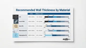
The design goal: maintain consistent, smooth transitions. Where thickness changes are unavoidable, use gradual 3:1 tapers to minimize stress concentration and flow hesitation. Generally, keep maximum wall thickness below 5mm to avoid excessive cycle times and poor mechanical properties from uneven cooling.
Draft Angles
Draft—a slight taper on vertical walls—is essential for parts to release cleanly from the mold without drag, scratching, or sticking. Insufficient draft causes production stoppages and accelerates mold damage. Textured surfaces require significantly higher draft angles—typically 1.5° per 0.001 inch of texture depth.
Draft recommendations by surface finish:
- Smooth/polished surfaces: 0.5–1° minimum (1–2° preferred)
- Light texture: 3° minimum
- Heavy texture: 5°+ minimum
- Complex texture (leather, snakeskin): 5–12° depending on depth
Material properties also influence draft requirements. Nylon's low coefficient of friction tolerates 0° draft (though 1° is recommended), while polycarbonate's higher surface friction demands 1.5° minimum. Never assume a standard 1° draft is sufficient—always cross-reference with the specific texture standard specified for the part.
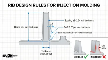
Rib and Boss Design
Ribs add structural strength without adding excessive wall mass, but rib thickness must be carefully controlled. The intersection of a rib and wall creates a thick section that cools slowly, pulling the surface inward to create visible sink marks.
Rib design rules:
- Thickness: 50–60% of nominal wall thickness maximum
- Height: ≤3.0× nominal wall thickness
- Spacing: ≥2.0–2.5× wall thickness apart
- Draft: 0.5° per side minimum
- Base radius: 0.25–0.4× wall thickness
Bosses (for screw inserts or standoffs) follow similar principles. Connect bosses to walls with ribs or gussets for stability rather than leaving them as isolated features. Include 0.5° draft on both inner and outer diameters. Design boss wall thickness to avoid creating thick sections that will sink.
Gate Location and Type
The gate is where molten plastic enters the mold cavity. Its location determines weld line placement, material flow patterns, pressure distribution, and potential cosmetic blemishes. Improper gating leads to warping, fill imbalances, structural weak points, and visible gate scars on customer-facing surfaces.
Gate location strategies:
- Position gates to ensure balanced filling—extremities fill last to allow venting
- Use simulation to predict weld line locations and move them away from high-stress areas or critical cosmetic surfaces
- Maintain high melt temperature (no more than 20°C below injection temp) when flow fronts meet to maximize weld line strength
- Consider flow length-to-thickness (L/t) ratios—large parts may require multiple gates to fill without excessive pressure
Gate type selection (edge, submarine, hot runner, valve) depends on part geometry, production volume, cosmetic requirements, and tooling budget. Getting this right before steel is cut matters — at EVOK, gate location is determined through mold flow analysis during the DFM phase so filling dynamics are confirmed, not assumed.
Undercuts
Undercuts are features that prevent a part from ejecting straight out of the mold — internal threads, hooks, recessed snaps, or any geometry that "locks" the part to the core.
Resolving them requires additional mold mechanisms like lifters or side-actions (sliders), which add 50%+ to tooling cost and increase maintenance complexity.
Cost implications:
- Simple two-plate molds: $3,000–$10,000
- Molds with side-actions/undercuts: $10,000–$25,000+
Minimize or redesign undercuts wherever possible. Consider alternatives like:
- Pass-through cores that can be pulled straight
- Sliding shutoffs that don't require active mechanisms
- Hand-loaded inserts for low-volume production (increases cycle time but reduces tooling cost)
- External threads instead of internal threads
- Snap-fit designs that use material deflection rather than mechanical undercuts
Every eliminated undercut reduces tooling cost, simplifies maintenance, and improves production reliability.
Weld Lines and Surface Texture
Weld lines form where two flow fronts meet inside the mold cavity. They appear as visible lines on the surface and can reduce mechanical strength by 50-60% in fiber-filled materials. Weld line location is influenced by gate placement, wall geometry, mold temperature, and injection speed.
Weld line management:
- Use mold flow simulation to predict locations before tooling
- Adjust gate positions to move weld lines to non-critical areas
- Increase melt temperature and injection speed to improve knit strength
- Avoid placing weld lines in high-stress load paths
Surface texture serves multiple purposes: aesthetic appeal, improved grip, and masking minor cosmetic defects like slight sink or weld lines. However, texture adds draft angle requirements — deeper textures demand steeper draft to release from the mold. EVOK's texture specification reference — shared during DFM review — maps required draft angles from 1° for ultra-fine textures up to 9° for heavy patterns, so teams can align surface finish decisions with mold geometry early.
What Does a DFM Report Include?
A DFM report is the formal deliverable of the DFM analysis process: a structured document that communicates how the part design will be interpreted for tooling, where risks exist, and what modifications are recommended before steel is cut. It bridges the design team and the mold manufacturer with a shared, documented understanding.
Typical DFM Report Sections
Core design decisions:
- Gate type and location with rationale
- Ejector pin placement and count
- Parting line location and shut-off surfaces
- Lifter and slider locations (if undercuts are present)
- Cooling channel layout strategy
Design analysis:
- Wall and rib thickness analysis with color-coded thickness maps
- Draft angle analysis showing adequate vs. insufficient draft zones
- Tolerance review and process capability assessment
- Material flow length-to-thickness (L/t) ratios
Recommendations:
- Design optimization suggestions with before/after comparisons
- Material selection validation or alternatives
- Cosmetic surface considerations
- Assembly and secondary operation requirements
All sections should include annotated images showing each decision on the actual part geometry. Generic text without visuals tells the design team nothing actionable.
Of all report components, Mold Flow Analysis produces the densest simulation data — and the most specific visual evidence of potential problems.
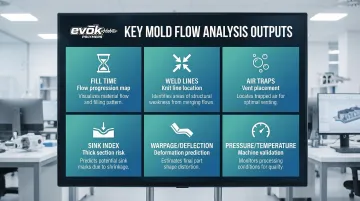
Mold Flow Analysis (MFA)
Mold Flow Analysis is a simulation-based component often included in comprehensive DFM reviews. Software simulates how plastic will flow, cool, and shrink inside the mold, identifying problems before any metal is machined. MFA can prevent defects and deliver 25% raw material cost savings through optimization.
Key MFA outputs:
- Fill time: Maps flow progression across the cavity to catch hesitation zones and unbalanced filling early
- Weld lines: Predicts location and severity (meeting angle) of weld lines
- Air traps: Flags where trapped air can cause burns or voids, directly informing vent placement decisions
- Sink index: Highlights areas prone to sink marks due to thick sections
- Warpage/deflection: Quantifies post-molding deformation caused by uneven shrinkage across the part
- Pressure/temperature: Validates machine capability and process window
Leading MFA tools include Autodesk Moldflow (the industry standard) and Moldex3D (known for high-accuracy 3D simulation). At EVOK, mold flow studies using Autodesk Moldflow Insight are built into every pre-tooling DFM review — clients see and resolve problems virtually before any tooling dollars are spent.
Quality Signals in DFM Reports
The quality of a DFM report reflects the expertise of the molding partner. A thorough review includes:
- Clear annotated visuals on actual part geometry
- Material-specific recommendations based on resin properties
- Quantified simulation data (fill times, pressures, temperatures)
- Specific, actionable design recommendations with technical rationale
- Transparent discussion of risks and tradeoffs
A cursory review — generic observations, no simulation data, no annotated visuals — leaves real problems undiscovered until tooling is already underway. At that stage, fixes cost multiples of what they would have in the design phase. The detail level of the DFM report is one of the clearest indicators of how seriously a molding partner takes the pre-tooling process.
DFM vs. DFA vs. DFMEA: What's the Difference?
These acronyms represent distinct but complementary engineering disciplines, each addressing different aspects of product development:
DFM (Design for Manufacturability) optimizes how individual parts are made. In injection molding, this means refining wall thickness, draft angles, gate locations, and geometry to ensure parts can be molded efficiently and defect-free.
DFA (Design for Assembly) optimizes how parts fit and assemble together. It aims to reduce total part count and ensure components are easy to handle, orient, and join. Techniques include designing snap-fits to eliminate screws, creating self-aligning features, and minimizing assembly steps.
DFMEA (Design Failure Mode and Effects Analysis) is a risk management tool that systematically maps potential failure modes, their causes, and downstream effects. It assigns severity, occurrence, and detection ratings to prioritize mitigation efforts.
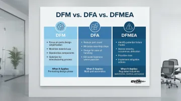
DFMEA is mandated in automotive (IATF 16949) and highly regulated in medical device (FDA/ISO 13485) and aerospace sectors — industries where design risk must be formally documented before production begins.
When Each Applies in Injection Molding
- DFM: Most critical during part design and pre-tooling phases
- DFA: Important when the molded part is one component in a larger assembled product
- DFMEA: Typically applied in regulated industries where design risk must be formally documented and mitigated
In practice, these disciplines overlap more than they compete. A thorough DFM review might flag a thin wall likely to fail under load — which is a DFMEA risk — and the fix might also simplify how the part snaps into an assembly, delivering a DFA benefit in the same move. Experienced molding partners treat all three as part of a single design review, even when only one is formally required.
Frequently Asked Questions
What is DFM in injection molding?
DFM is the process of optimizing a plastic part's geometry for efficient, defect-free injection molding before tooling begins. It addresses wall thickness, draft angles, gate locations, and geometric features to reduce cost, prevent defects, and avoid production delays.
What are the 5 principles of DFM?
The five core principles of DFM are:
- Simplify geometry to reduce mold complexity
- Standardize features to proven design rules
- Design for specific material behavior and properties
- Minimize secondary operations by building complete features into the mold
- Design for realistic tolerances that match normal process variation
What is a DFM checklist?
A DFM checklist is a structured list of design criteria reviewed before tooling, covering wall thickness uniformity, draft angles, rib-to-wall ratios, gate location, undercut presence, parting line placement, and material-specific requirements. It systematically identifies and resolves design risks before mold fabrication begins.
How to design for manufacturability?
Start DFM before CAD is finalized — not after. Partner with an experienced mold manufacturer for design review, use mold flow analysis to validate decisions, and follow established design rules for your resin and geometry. The key discipline: challenge every feature to confirm it adds value worth its manufacturing complexity.
What are the design requirements for injection molding?
Core requirements for injection-molded parts include:
- Wall thickness appropriate to the material (typically 1.0–3.5mm)
- Draft on all vertical surfaces (minimum 0.5–1°; more for textured finishes)
- Gate location that controls flow direction and weld line placement
- Radii on all corners to reduce stress concentration
- Rib thickness at 60% or less of nominal wall thickness
- Tolerances matched to realistic process capability (±0.003–0.005 inches)
What is DFA, DFM, and DFMEA?
DFM optimizes how a part is manufactured; DFA focuses on how parts assemble into a finished product. DFMEA takes a different approach — it identifies and documents potential failure modes before they reach production. DFMEA is especially critical in regulated industries like automotive and medical devices, where design risk must be formally tracked and mitigated.