Introduction
Injection molding defects drain profits through a hidden efficiency gap: median machine runtime sits at just 71% compared to 97% for top performers. That 26-point difference represents massive capacity lost to defect-related downtime, scrap, and rework.
For manufacturers, defects create immediate financial pain—increased material costs, production delays, and expensive secondary operations. Downstream consequences multiply: assembly problems, field failures, warranty claims, and damaged brand reputation.
This guide delivers actionable solutions:
- Identify the 10 most common injection molding defects
- Understand root causes across design, process, and material factors
- Implement proven prevention strategies that reduce waste while maintaining quality
Key Takeaways
- Defects range from surface blemishes to structural failures costing thousands per production run
- Fix issues at the source: incorrect process settings, poor material prep, or flawed mold design
- Prevent defects through DFM reviews, proper material handling, and process validation
- Catch problems early with real-time monitoring before full production begins
- Sustain quality through statistical process control and manufacturing partnerships
What Are Injection Molding Defects?
Injection molding defects are imperfections in molded parts that affect appearance, function, or structural integrity.
These flaws occur when material flow, cooling, or ejection deviates from design parameters, resulting in parts that fail to meet specifications.
Defects fall into three severity categories:
- Minor (Cosmetic): Flow lines, slight discoloration—acceptable for hidden components but unacceptable for Class A surfaces on consumer products
- Major (Functional): Warping, dimensional distortion—parts won't fit assemblies or meet tolerance requirements
- Critical (Safety): Delamination, cracks—structural failures that create safety risks, particularly in automotive and medical applications
This classification framework helps manufacturers prioritize prevention efforts and set acceptance criteria based on part function and visibility.
10 Most Common Injection Molding Defects
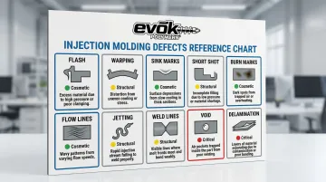
Understanding common injection molding defects helps you prevent costly production issues and maintain part quality. The defects below are organized from cosmetic surface issues to more serious structural problems.
| Defect | Severity | Primary Cause | Quick Fix |
|---|---|---|---|
| Flow Lines | Cosmetic | Low injection speed | Increase speed/temperature |
| Sink Marks | Cosmetic/Structural | Inadequate packing | Increase packing pressure |
| Warping | Structural | Uneven cooling | Balance cooling channels |
| Short Shots | Critical | Insufficient fill | Increase pressure/temperature |
| Flash | Cosmetic | Excess pressure | Reduce injection pressure |
| Weld Lines | Structural | Poor flow convergence | Optimize gate location |
| Burn Marks | Cosmetic/Material | Trapped air | Improve venting |
| Delamination | Critical | Contamination/moisture | Dry resin thoroughly |
| Vacuum Voids | Structural | Inadequate packing | Reduce wall thickness |
| Jetting | Cosmetic | High gate velocity | Reduce injection speed |
Flow Lines
Appearance: Wavy patterns or streaks of slightly different color on the part surface, typically radiating from gate locations.
Causes:
- Low injection speed causing material to cool prematurely as it flows
- Inconsistent wall thickness creating uneven cooling rates
- Insufficient injection pressure or mold temperature
Flow lines are primarily cosmetic but signal suboptimal process settings. Consumer-facing products require defect-free surfaces, making these patterns unacceptable for visible components.
Prevention: Maintain uniform wall thickness, increase injection speed and pressure, raise mold temperature, and optimize gate placement to ensure consistent material flow.
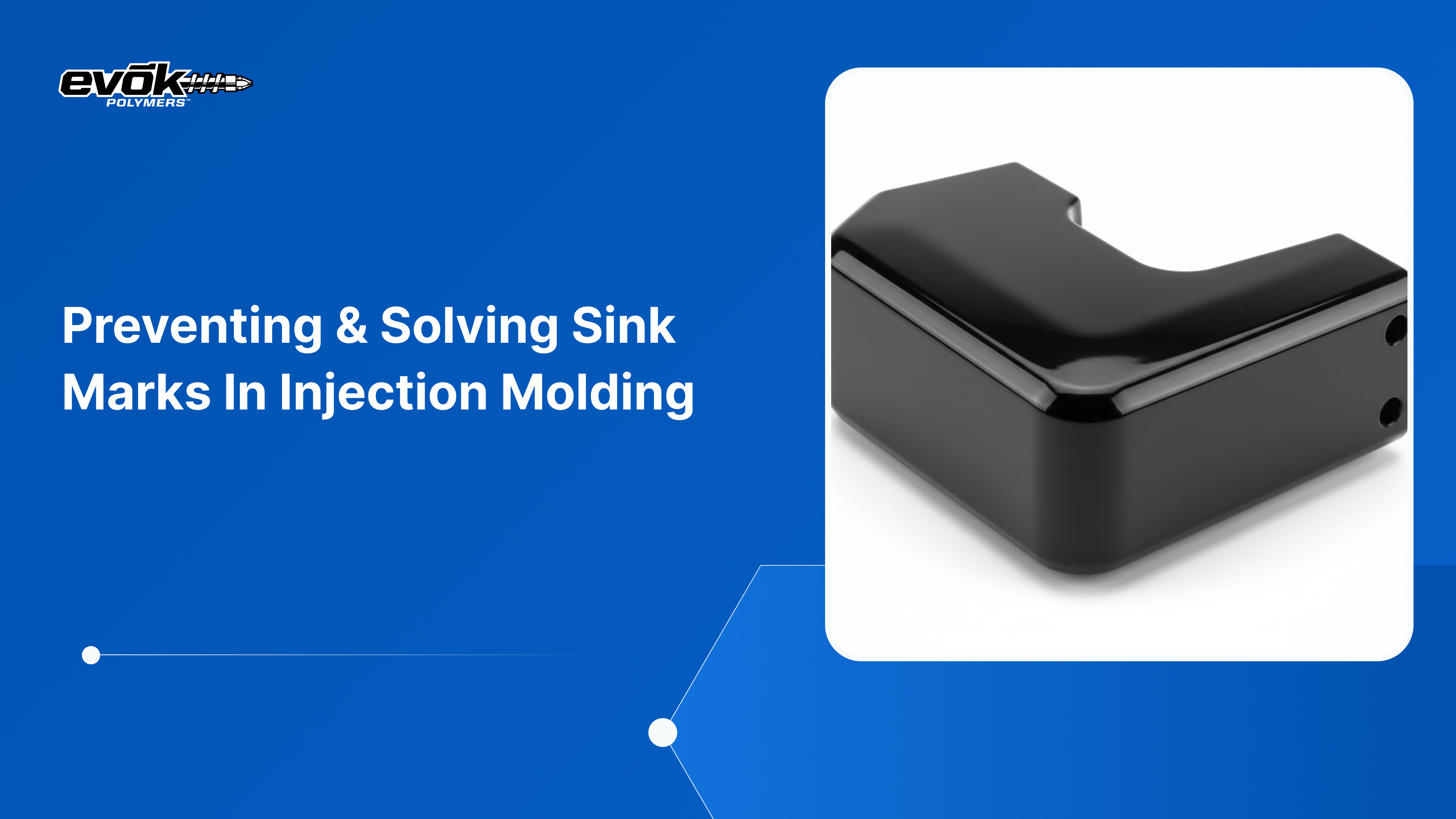
Sink Marks
Appearance: Small depressions or craters on the surface, typically appearing in thick sections or above ribs.
Causes:
- Inner portions of thick sections shrink faster than outer surfaces during cooling
- Insufficient packing pressure failing to compensate for material shrinkage
- Premature gate freeze-off preventing additional material from entering the cavity
- Rib thickness exceeding 50-70% of adjacent wall thickness
Sink marks signal inadequate packing and can weaken part structure beneath the surface depression.
Prevention: Core out thick sections, increase packing pressure and hold time, maintain proper rib-to-wall thickness ratios (50-70%), and ensure adequate gate freeze time.
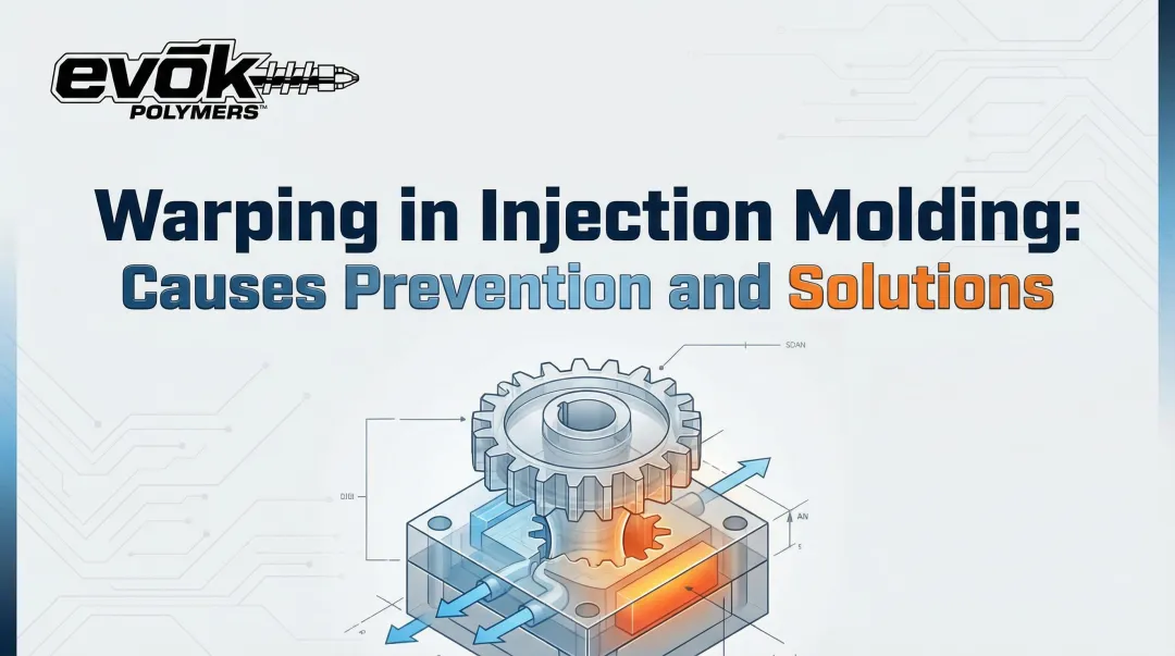
Warping
Appearance: Unintended bending, twisting, or dimensional distortion where parts don't lie flat or match specifications.
Causes:
- Uneven cooling creating internal stresses that deform the part
- Non-uniform wall thickness causing differential shrinkage
- Excessive injection speed
- Semi-crystalline resins (more prone to warping than amorphous materials)
This serious defect prevents proper fit during assembly and compromises part function, often requiring expensive rework or part rejection.
Prevention: Design for uniform wall thickness, balance cooling channels, reduce injection speed, select low-shrinkage materials, and ensure adequate cooling time before ejection.
Short Shots
Appearance: Incomplete parts where the mold cavity wasn't fully filled, resulting in missing features or sections.
Causes:
- Insufficient injection pressure or material volume
- Material viscosity too high (temperature too low)
- Blocked or undersized gates restricting flow
- Trapped air preventing complete cavity fill
- Wall thickness below 0.8mm (too thin for material to flow completely before solidifying)
Short shots typically render parts completely unusable, making this a major defect category.
Prevention: Increase injection pressure and temperature, improve venting, select lower viscosity resin, enlarge gates, and maintain minimum wall thickness of 0.8mm.
Flash (Burrs)
Appearance: Thin fins of excess material protruding from parting lines, vents, or ejector pin locations.
Causes:
- Excessive injection pressure forcing material into mold gaps
- Worn or misaligned mold halves creating gaps at parting lines
- Insufficient clamping force allowing mold to separate slightly
- Mold temperature too high reducing material viscosity
- Overpacking during hold phase
Flash requires secondary trimming operations, adding cost and cycle time. Beyond the immediate trimming costs, severe flash signals progressive mold wear requiring maintenance.
Prevention: Optimize clamp tonnage, repair worn shut-off surfaces, reduce injection pressure, lower mold temperature, and adjust packing pressure.
Weld Lines (Knit Lines)
Appearance: Visible lines or seams where two flow fronts meet after flowing around holes, cores, or other obstacles.
Causes:
- Flow fronts cooling too much before converging, preventing proper fusion
- Low mold temperature
- Insufficient injection pressure or speed
- Material viscosity too high
These lines create weak points vulnerable to stress failure. While cosmetically undesirable, the structural weakness poses the greater concern for load-bearing components.
Prevention: Increase melt and mold temperature, optimize gate location to move weld lines to non-critical areas, improve venting at convergence points, and increase injection speed.
Burn Marks
Appearance: Black or rust-colored discoloration, typically on edges or at the end of fill opposite the gate.
Causes:
- Trapped air overheating in the cavity (dieseling effect — rapid air compression generating heat)
- Excessive injection speed compressing air rapidly
- Inadequate venting preventing gas escape
- Material degradation from excessive barrel temperature or residence time
Severe burns indicate material degradation that affects mechanical properties beyond just appearance.
Prevention: Add or enlarge vents, reduce injection speed, lower melt temperature, decrease screw RPM, and ensure proper material residence time.
Delamination
Appearance: Thin surface layers peeling or flaking off, similar to mica flakes separating from the part.
Causes:
- Contamination of resin with incompatible materials
- Excessive moisture in hygroscopic materials (particularly polycarbonate >0.02% moisture)
- Overuse or incompatibility of mold release agents
- Incompatible material blends or regrind contamination
This critical defect dramatically reduces part strength, potentially creating safety hazards in load-bearing or structural applications.
Prevention: Ensure material purity, dry hygroscopic resins thoroughly per manufacturer specifications, avoid incompatible release agents, and properly manage regrind ratios.
Vacuum Voids (Air Pockets)
Appearance: Trapped air bubbles visible as voids beneath the surface, especially in thick sections exceeding 4mm.
Causes:
- Inadequate packing pressure allowing voids to form as material cools
- Rapid cooling of outer surfaces trapping air inside
- Material density changes during solidification
- Thick sections without adequate packing support
Voids weaken parts internally, even when not visible on the surface. The 4mm threshold represents the point where outer surfaces solidify faster than internal material can pack, creating vacuum pockets.
Prevention: Maintain consistent wall thickness, use ribs instead of thick masses, increase packing pressure and hold time, and design sections under 4mm thick.
Jetting
Appearance: Squiggly snake-like flow patterns on the surface, typically spreading from the gate.
Causes:
- Material squirting through small gate at high velocity and solidifying before the cavity fills
- Gate opening into open space rather than against a wall
- Excessive injection pressure with inadequate gate size
The solidified material stream gets pushed along the cavity surface, creating weak flow lines and poor surface finish that compromise both appearance and structural integrity.
Prevention: Reduce initial injection speed, use fan or overlap gates, direct gate flow against a wall surface, increase melt temperature, and enlarge gate opening.
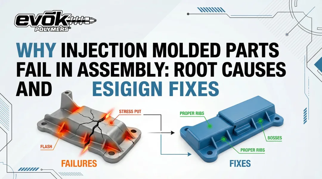
What Happens If Injection Molding Defects Are Ignored
Immediate Production Impacts
Ignoring defects creates direct financial losses:
- Increased scrap rates — rejected parts waste material and machine time
- Secondary operations costs — trimming flash or reworking parts adds labor and extends cycle times
- Production delays — quality holds disrupt delivery schedules
In automotive applications, warranty claims and recall costs averaged $11.8 billion for US-based OEMs and suppliers in 2016. The supplier share of recall costs has tripled in recent years.
Downstream Consequences
Parts that pass initial inspection but contain hidden defects cause assembly problems, field failures, product recalls, and warranty claims. This damages brand reputation and customer relationships.
The cost of fixing defects multiplies dramatically the further downstream they're discovered—what costs $1 to fix in design costs $10 in tooling, $100 in production, and $1,000 in the field.
Safety and Compliance Risks
In regulated industries, defects carry severe consequences:
- Automotive — IATF 16949 standards require Cpk >1.67 (0.6 ppm defects) for critical dimensions
- Medical devices — manufacturing defects can trigger Class 1 recalls (e.g., implantable port separations posing serious injury or death)
- Legal exposure — defective parts create liability risks and regulatory violations
Beyond recalls, defective parts put manufacturers at risk for compliance violations and legal action.
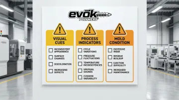
Warning Signs You're About to Experience Defects
Visual Cues:
- Inconsistent part appearance between consecutive shots
- Gradual changes in surface finish or gloss
- Visible material degradation, discoloration, or contamination
- Increasing frequency of minor cosmetic issues
Process Indicators:
- Cycle time variations from shot to shot
- Fluctuating injection pressures or fill times
- Temperature inconsistencies in barrel zones or mold
- Unusual machine sounds or vibrations
- Increasing cushion variability
Mold Condition Signals:
- Excessive wear visible on gates or parting lines
- Buildup of residue or deposits on mold surfaces
- Difficulty ejecting parts or sticking in cavity
- Increased maintenance frequency or unplanned stops
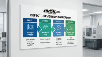
How to Prevent Injection Molding Defects
Optimize Part Design with DFM Principles
Maintain Uniform Wall Thickness:
- Target 1-3mm for most applications
- Material-specific ranges: ABS (0.045-0.140"), Polycarbonate (0.040-0.150"), Nylon (0.030-0.115")
- Ensures even cooling and material flow
- Prevents differential shrinkage that causes warping and sink marks
Add Appropriate Draft Angles:
- Minimum 1-2° on all vertical faces
- Reduce to 0.5° only in critical sizing areas
- Add 1° for every 0.001" of texture depth (3° for light texture, 5°+ for heavy)
- Facilitates part ejection and reduces stress
Include Proper Radii:
- Round all corners and transitions
- Improves material flow around features
- Reduces stress concentrations that can lead to failure
- Prevents flow hesitation that creates weld lines
Rib Design:
- Limit rib thickness to 50-70% of adjacent wall thickness
- Prevents sink marks on opposite surface
- Maintains structural support without creating thick sections
Set and Monitor Process Parameters
Establish Optimal Settings:
- Scientific molding principles determine ideal injection speed, pressure, and temperature
- Document proven parameter sets for each part/material combination
- Standard operating procedures based on validation data
- Mold flow analysis predicts optimal settings before production
Implement Process Monitoring:
- Track key variables: fill time, peak pressure, cushion, melt temperature
- Statistical Process Control (SPC) identifies trends before defects occur
- Cycle time consistency serves as an early warning indicator
- Real-time alerts flag parameter drift
Continuous Validation:
- Compare actual results against mold flow predictions
- Parameters adjusted based on first article qualification data
- All process changes and their effects documented
- Process capability (Cpk) maintained above industry standards
Implement Proper Material Handling
Pre-dry Hygroscopic Materials (moisture-absorbing resins):
- Polycarbonate: 120°C for 4 hours (max moisture 0.02%)
- Nylon 6/6: 71-77°C per manufacturer specifications
- PBT: 110°C, PET: 135°C
- Moisture above specifications causes hydrolysis, brittleness, and splay marks
Prevent Moisture Reabsorption:
- Store dried materials in sealed containers with desiccant
- Use drying hoppers with continuous hot air circulation
- Minimize exposure time between drying and processing
- Monitor moisture content regularly with moisture analyzers
Rotate Inventory:
- Implement FIFO (first-in, first-out) system
- Prevent material degradation from aging or UV exposure
- Track lot numbers for traceability
- Avoid mixing different material lots without validation
Maintain Mold Tooling Regularly
Establish Preventive Maintenance Schedules:
- Base schedules on shot count and manufacturer recommendations
- P20 steel molds: maintenance every 100,000-250,000 shots
- H13 hardened steel: every 250,000-500,000 shots
- Weekly cleaning for glass-filled materials to prevent abrasive wear
Regular Cleaning:
- Clean mold surfaces, gates, and vents to prevent buildup
- Remove residue that affects flow and venting
- Use appropriate cleaning methods that don't damage mold surfaces
- Document cleaning procedures and frequency
Inspection and Repair:
- Inspect parting lines for wear that causes flash
- Check ejector pins for damage or sticking
- Examine cooling lines for blockages or leaks
- Repair worn surfaces before they affect part quality
- Replace worn components proactively
Mold Lifespan Management:
- P20 steel: 100,000-500,000 shots typical
- H13 hardened steel: 1+ million shots with proper maintenance
- Maintenance is the primary variable—proper care can double mold life
- Track shot count and plan for refurbishment or replacement
Partner with Experienced Molding Experts
Even with rigorous maintenance and process control, complex defect challenges benefit from specialized expertise.
Leverage Design Expertise:
Injection molding specialists conduct comprehensive mold flow analysis during design to predict and prevent defects before tooling investment. Experienced partners provide systematic defect troubleshooting across resin/additive issues, process parameters, and mold design problems.
Tools like Autodesk Moldflow Insight analyze filling dynamics, identify potential weak points like knit lines, and recommend design changes that eliminate defect risks before production begins.
Access Process Optimization:
Partners with deep industry knowledge bring proven optimization methodologies. Scientific molding approaches use systematic trial processes where T1 samples demonstrate 90% of final part performance, enabling parameter refinement before full production.
First article qualification processes with 30+ inspection points per cavity for critical dimensions ensure process capability through Cp/Cpk analysis before locking down production settings.
Benefit from Material Selection Guidance:
Expert partners help navigate material selection to prevent moisture sensitivity, degradation, and compatibility issues. Comprehensive material selection services cover moisture resistance, UV resistance, chemical resistance, and heat deflection properties. EVOK guides clients through commodity, engineered, and specialty grade options while considering cost and availability tradeoffs—drawing on 25 years of injection molding experience to match materials with application requirements.
Tips for Long-Term Defect Prevention and Control
Preventing injection molding defects requires more than fixing immediate problems. Sustainable quality comes from systematic monitoring, continuous training, and data-driven decision-making.
Implement Statistical Process Control (SPC):
- Track injection pressure, melt temperature, shot weight, and cycle time continuously
- Establish control limits based on process capability studies
- Identify trends before they result in defects
- Use control charts to visualize process stability
Train Operators Thoroughly:
- Educate on defect recognition and classification
- Teach root cause analysis techniques
- Establish clear response procedures for common issues
- Empower operators to stop production when parameters drift
Maintain Detailed Documentation:
- Record parameter settings for each tool and material pairing
- Document defect history and corrective actions taken
- Track process changes and their effects on quality
- Create knowledge base for troubleshooting
Establish Continuous Improvement Culture:
- Conduct regular process reviews with cross-functional teams
- Partner with molders who prioritize optimization through collaborative problem-solving
- Share learnings across similar parts and applications
- Invest in ongoing training and technology upgrades
EVOK demonstrates this approach through cross-functional collaboration. Their team combines senior industrial designers, mechanical engineers, and manufacturing specialists on every project.
Each component moves through a five-stage development pipeline examining ergonomics, fit and function, tolerance stacking, and lifecycle performance—catching potential defects before tooling begins.
Conclusion
Injection molding defects stem from identifiable root causes in four key areas: design, process control, material handling, and tooling condition. Understanding these causes empowers manufacturers to prevent defects proactively rather than reacting to quality failures.
Prevention strategies deliver dramatic cost savings compared to post-production fixes:
- Design for manufacturability: Optimized wall thickness, proper gate placement, and adequate draft angles
- Process optimization: Validated temperature, pressure, and cooling parameters
- Material management: Proper drying, storage, and handling protocols
- Mold maintenance: Regular cleaning, inspection, and preventive repairs
The cost multiplier is stark: what costs $1 to prevent in design costs $1,000 to fix in the field.
Partnering with experienced molding specialists accelerates defect prevention from the design phase forward. Companies like Evok Polymers combine 25 years of injection molding expertise with mold flow analysis, scientific molding principles, and cross-functional design reviews to identify potential defects before tooling begins. This upfront collaboration delivers consistent, defect-free production and speeds your time to market.
Frequently Asked Questions
What are the common injection molding defects?
The 10 most common defects are flow lines, sink marks, warping, short shots, flash, weld lines, burn marks, delamination, vacuum voids, and jetting. These range from cosmetic surface issues to structural problems that compromise part integrity.
What are the plastic molding defects?
Plastic molding defects in injection molding are the same as those listed above. However, specific defects vary by molding process—blow molding, rotational molding, and thermoforming each have their own characteristic defect profiles based on different material flow and cooling dynamics.
What are the defects of polycarbonate injection molding?
Polycarbonate is susceptible to burn marks from high processing temperatures, moisture-related defects like splay and brittleness (requires drying to <0.02% moisture at 120°C for 4 hours), and environmental stress cracking from rapid cooling or chemical exposure under stress.
What are the defects of mold material?
Mold material defects affect the mold itself: parting line wear causing flash, corrosion creating poor surface finish, damaged cooling lines, and worn ejector pins causing part sticking. Proper mold steel selection (P20 vs. H13) and preventive maintenance prevent these issues.
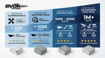
How long does an injection mold last?
Mold life varies by material and volume: prototype aluminum molds (<500 shots), low-volume mild steel (<100K shots), medium-volume P20 steel (100K-500K shots), and high-volume H13 hardened steel (1M+ shots). Proper maintenance can double effective mold life.
What are the 4 stages of injection molding?
The four stages are: 1) Clamping - mold closes and locks under tonnage to prevent opening, 2) Injection - molten plastic fills the cavity under pressure, including packing and holding phases, 3) Cooling - part solidifies in the mold (typically longest stage), 4) Ejection - mold opens and pins push the part out. Defects can originate in any stage.