Introduction
Warping ranks among the top three defects in injection molding, accounting for up to 30% of rejected parts in high-precision manufacturing. When a carefully designed component emerges from the mold only to bend, twist, or bow as it cools, the impact is immediate and costly.
The consequences include:
- Assembly failures that halt production lines
- Customer returns and warranty claims
- Thousands of dollars in scrapped parts
- Delayed product launches
This guide explores the root causes of warping, proven prevention strategies during design and tooling, and practical solutions to correct warping issues in production.
Key Takeaways
- Warping stems from uneven cooling rates that create internal stresses and part deformation
- Non-uniform walls, temperature imbalances, and inadequate pressure drive most warping defects
- Design with uniform wall thickness and optimized cooling to prevent warping at the source
- Fine-tune holding pressure, cooling time, and temperatures to eliminate warping post-tooling
- Moldflow simulation cuts warpage prediction error to 16% before you invest in production tools
What Is Warping in Injection Molding?
Warping is the bending, twisting, bowing, or curling of a molded part after ejection from the mold, caused by internal stresses from differential shrinkage. When different sections of a part cool and solidify at different rates, the resulting forces deform the part once it's removed from the rigid mold cavity.
Common warping patterns include:
- Flat panels that bow upward or downward
- Rectangular housings that twist at the corners
- Long thin parts that curl along their length
What sets warping apart from defects like sink marks (localized surface depressions) or voids (internal air pockets) is its impact on the entire part geometry. It's not just a cosmetic issue—warped parts often fail to meet dimensional tolerances, preventing proper assembly or function.
Research shows that warpage compromises dimensional and shape stability, causing parts to fail design specifications and often rendering them as scrap.
Common Causes of Warping
Warping in injection molded parts stems from several interconnected factors—material behavior, part geometry, mold design, and process settings. Identifying which cause applies to your specific part is essential for selecting the right fix.
Differential Cooling Rates
Uneven cooling across the part creates temperature gradients that cause some areas to solidify and shrink faster than others, building up internal stress.
When the part is ejected while these stresses remain locked in, it deforms to relieve the tension.
This typically happens when:
- Thick sections cooling slower than thin sections
- One mold half running hotter than the other
- Inadequate cooling channel design creating hot spots
- Poor heat transfer in areas far from cooling lines
Industry guidelines specify that core-to-cavity temperature differential should not exceed 5°C to avoid uneven shrinking and subsequent warpage.
Molecular and Fiber Orientation
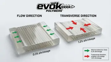
Beyond cooling rates, the filling process itself introduces warping risk. Shear forces during filling cause polymer molecules (and glass fibers if present) to align in the direction of flow.
This alignment leads to anisotropic shrinkage—meaning the material shrinks more perpendicular to flow than along it, creating directional stresses that warp the part.
Materials most affected include:
- Semi-crystalline materials (PP, PE, nylon) are especially prone to orientation effects due to their ordered molecular structure
- Fiber-filled materials shrink less in the direction of fiber alignment, creating high differential shrinkage
- Glass fibers reduce shrinkage in the flow direction but not transversely, making anisotropy a primary cause of warpage in reinforced parts
Non-Uniform Wall Thickness
Part geometry plays a critical role. Variations in wall thickness create different cooling rates and packing densities.
Thick sections shrink more than thin sections and cool slower, pulling the part out of shape as internal stresses develop.
Watch for these design issues:
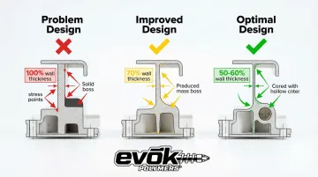
- Ribs that are too thick relative to nominal wall (should be 50-70% of base wall)
- Abrupt transitions between thick and thin areas
- Heavy gate areas versus thin end-of-fill regions
- Localized thick sections like bosses or mounting posts
Maintaining uniform wall thickness is the "number one rule" for plastic part design to reduce differential shrinkage and warping.
Inadequate Packing and Holding Pressure
Even with good part design, process settings can introduce warping. Insufficient holding pressure or holding time allows the material to shrink excessively as it cools.
If packing is uneven across the part—with some areas receiving more pressure than others—differential shrinkage and warping result.
Packing problems often trace to:
- Gate freeze-off occurring too early, cutting off pressure to the cavity
- High pressure drop from gate to end-of-fill, leaving distant areas underpacked
- Holding time too short to compensate for material shrinkage
- Studies show holding pressure is the most significant factor (p < 0.01) in reducing shrinkage
Mold Temperature Imbalances
Finally, mold temperature control directly affects warping. Uneven mold surface temperatures—whether between core and cavity or across the part surface—cause one side of the part to cool faster.
This creates through-thickness shrinkage differences that bow the part toward the side with higher shrinkage (typically the hotter side).
Common causes:
- Poorly designed cooling lines with uneven channel spacing
- Blocked or scaled cooling channels reducing heat transfer
- Hot spots in thick mold sections far from cooling
- Cold spots where cooling channels are too close to the cavity surface
What Happens If Warping Is Ignored
The operational and financial impacts of warping are significant and far-reaching. Warped parts fail dimensional inspection, don't fit into assemblies, and require costly rework or scrap.
This leads to production delays, customer returns, and substantial financial losses.
In a documented Six Sigma case study, high defect rates due to deformation were the primary customer complaint. By reducing these defects through process optimization, the manufacturer achieved estimated savings of approximately $750,000 USD based on monthly production of 100,000 units.
Warning Signs You're About to Experience Warping
Catching these early indicators helps molders address warping before it becomes a recurring issue:
- Delayed dimensional failures: Parts pass inspection immediately after molding but fail checks hours or days later as internal stresses relax. Studies on polypropylene show significant dimensional changes up to 168 hours after injection.
- Visible deformation: Bowing, twisting, or curling becomes apparent. Parts rock on flat surfaces or show gaps when test-fitted into assemblies.
- Ejection difficulties: Difficulty closing molds or ejecting parts indicates high residual stress, often a precursor to post-ejection warping.
How to Prevent Warping
Prevention requires a set of proactive design, tooling, and process strategies that eliminate the root causes of differential shrinkage before production begins.
Design for Uniform Wall Thickness and Geometry
Maintain constant wall thickness throughout the part, using gradual transitions between sections and avoiding heavy ribs or bosses that create thick-thin imbalances. Adjacent walls should be no less than 40-60% of the primary wall thickness, with transitions tapered gradually to avoid stress concentrations.
Following DfM principles during the design phase can eliminate geometry-related warping risks before tooling is cut. Design reviews, tolerance analysis, and functional assessments help identify and correct potential issues early.
EVOK's approach integrates DfM analysis immediately following initial part model approval, with optional final design changes implemented based on manufacturability findings.
Key design guidelines:
- Keep wall thickness below 5mm where possible
- Design ribs at 50-70% of nominal wall thickness
- Space ribs at least 2-2.5 times the nominal wall apart
- Use gradual transitions (not abrupt steps) between thick and thin sections
Optimize Mold Cooling System Design
Once the part geometry is optimized, cooling system design becomes critical. Design cooling channels to provide uniform and balanced cooling to all areas of the part, with particular attention to thick sections and core/cavity temperature matching.
Cooling channels should be spaced 3-5 times the channel diameter apart and positioned approximately 2-2.5 times the diameter away from the cavity surface.
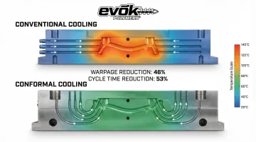
Mold flow studies and thermal simulations can validate cooling circuit designs and predict temperature distributions before the mold is built.
Advanced conformal cooling channels can reduce warpage by 46% compared to conventional cooling, while also reducing cycle times by 53%.
Working with a molder who has deep tooling expertise and proprietary cooling strategies can result in molds that inherently resist warping.
EVOK uses Autodesk Moldflow Insight to predict temperature distributions and optimize cooling channel placement before steel is cut, ensuring balanced thermal management from the start.
Select Materials with Lower Shrinkage and Warpage Tendency
Material selection impacts warping significantly. Amorphous resins (ABS, PC, PS) generally warp less than semi-crystalline resins (PP, PE, POM, nylon), with shrinkage rates typically below 0.7% versus 1-3% for crystalline materials.
Glass-filled materials require careful gate and flow design to manage fiber orientation. While fibers reduce shrinkage in the flow direction, they create directionally dependent shrinkage that can cause warping if not controlled.
Material selection considerations:
- Polycarbonate (PC) shows low shrinkage: 0.005-0.007 inches
- Polypropylene (PP) exhibits higher shrinkage: 0.010-0.030 inches
- Fiber-filled grades require symmetric gating to balance orientation
- Consult with material suppliers and molders to choose grades with predictable shrinkage behavior
Control Process Parameters for Uniform Packing and Cooling
With the right material selected, process parameters become the final control point. Optimize injection speed, holding pressure, holding time, melt temperature, and mold temperature to ensure consistent part density and cooling rates.
Research shows that optimal combinations of injection temperature (260°C), packing pressure (40 bar), and packing time (2s) can reduce warpage by up to 98.32% compared to worst-case parameter sets.
Process optimization strategies:
- Gate into thick sections to minimize pressure drop
- Use multiple gates for large parts to balance packing
- Extend holding time until gate freeze-off to maintain cavity pressure
- Balance mold temperature within ±2°C between core and cavity
- Monitor zone temperatures closely during trials
Data-driven process development—using scientific molding principles or Six Sigma methodologies—can systematically eliminate warping by controlling the variables that cause differential shrinkage.
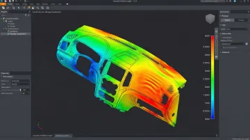
Use Simulation to Predict and Prevent Warping
Leverage mold flow analysis software to simulate filling, packing, cooling, and warpage before committing to tooling. The Moldflow 2024 STAMP model reduces average warpage prediction error from 77% to 16% across tested industrial parts by using measured shrinkage data to calibrate material properties.
Simulation identifies high-risk areas for warping and guides decisions on wall thickness adjustments, cooling channel placement, and material selection. In one documented case, simulation-guided "inverse contouring" (pre-compensating mold geometry for expected warp) reduced warpage by 82%, bringing values within a ±0.30mm range.
Validate and Lock Down the Process
Once you've achieved a warpage-free process, run process capability studies and use statistical process control to ensure it remains stable over time. Document and lock down all critical process parameters, train operators on the importance of consistency, and implement automated monitoring where possible.
Critical dimensions should receive multiple inspection points per cavity (30 for critical, 5 for non-critical) to detect any variation that could indicate developing warpage issues.
How to Fix Warping Issues in Production
If warping occurs despite prevention efforts, systematic troubleshooting of process parameters and tooling can often resolve the issue without redesigning the part.
Increase Holding Pressure and Holding Time
Raising holding pressure or extending holding time packs more material into the cavity, compensating for shrinkage and reducing the density differences that cause warping.
Increasing packing pressure from 30 to 50 bar significantly reduced warpage in controlled studies. Adjust these parameters in small steps (5-10% increases) while monitoring part dimensions with measurement tools or fixtures. Document changes and verify improvements with statistical sampling before locking in new settings.
Adjust Mold and Melt Temperatures
Raising mold temperature slows cooling and allows more uniform solidification, while lowering melt temperature can reduce overall shrinkage (though this must be balanced against flow and fill requirements).
Use pyrometers or thermal imaging to verify actual mold surface temperatures and ensure core and cavity are balanced within 5°C.
Temperature adjustment guidelines:
- Increase mold temperature in 5°C increments
- Verify both core and cavity temperatures separately
- Allow 10-15 cycles for thermal stabilization after changes
- Monitor for secondary effects (flash, longer cycles)
Extend Cooling Time in the Mold
Allowing parts to cool longer in the mold before ejection gives them more time to solidify fully and reduces the tendency to warp when ejected while still warm and soft.
This approach trades cycle time for part quality but often provides the simplest fix for minor warping issues.
Extend cooling time in 1-2 second increments, checking part temperature at ejection to ensure it's below the material's heat deflection temperature.
Rebalance or Modify Cooling Channels
When simple adjustments don't resolve the issue, the cooling system itself may need attention. Inspect cooling lines for blockages, leaks, or poor flow. Consider adding baffles, bubblers, or additional circuits to hot spots causing uneven cooling. In severe cases, tooling modifications may be necessary to achieve the uniform cooling required to eliminate warping.
Adding cooling near mounting bosses reduced warpage by over 70% in one documented case study.
Optimize Gate Location and Size
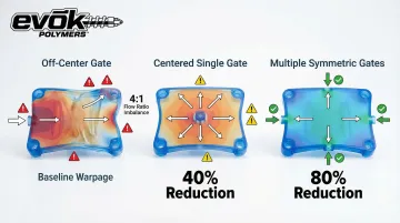
Relocating the gate to a thicker section or adding gates can reduce pressure drop and improve packing uniformity. An off-center gate creating flow ratio greater than 4:1 can lead to significant warpage, while using multiple gates or symmetric gating can reduce warpage by up to 80% compared to single-gate designs.
Enlarging gates extends the packing window and reduces freeze-off issues. Work with an experienced molder or tool designer to evaluate gate changes, as this may require mold modifications or inserts.
Best Practices for Long-Term Warpage Control
Preventing warpage isn't a one-time fix—it requires ongoing vigilance throughout production. Even well-optimized processes can drift over time due to equipment wear, environmental changes, or inconsistent practices.
Systematic quality control catches these issues before they become costly defects:
- Implement SPC monitoring — Track injection speed, holding pressure, cooling time, and mold temperature to detect drift early
- Conduct regular mold maintenance — Clean cooling lines quarterly and check ejector pin alignment
- Train operators thoroughly — Ensure technicians understand warping root causes and process consistency
- Use automated data logging — Real-time monitoring alerts operators to parameter deviations before warping occurs
- Document process windows — Maintain detailed records of acceptable ranges for each part and material
Production tooling designed with robust cooling systems and precision alignment reduces the maintenance burden. When mold design prioritizes uniform cooling and consistent ejection, operators spend less time troubleshooting warpage issues and more time maintaining steady output.
Regular reviews of process data help identify gradual shifts that might go unnoticed day-to-day. A holding pressure that drifts 5% lower over several weeks can introduce warpage without triggering immediate alarms, making statistical tracking essential for long-term control.
Conclusion
Warping has identifiable root causes—primarily differential shrinkage from uneven cooling, part geometry issues, and process imbalances. These causes can be systematically addressed through design optimization, mold engineering, and process control.
Prevention through proper design and tooling is far more cost-effective than fixing warping after tooling is complete.
The right manufacturing partner makes the difference. With 25 years of experience solving complex molding challenges, EVOK helps manufacturers minimize warping risk through:
- Mold flow analysis to predict and prevent warping before tooling
- DfM optimization to identify geometry and material concerns early
- Data-driven process development to control cooling and minimize differential shrinkage
- Collaborative problem-solving to address issues quickly when they arise
This upfront engineering approach delivers dimensionally stable parts with fewer iterations and lower total cost.
Frequently Asked Questions
What causes warping in injection molding?
Warping is caused by differential shrinkage when different areas of a part cool at different rates, creating internal stresses that deform the part after ejection. Root causes include non-uniform wall thickness, uneven mold temperatures, inadequate packing pressure, and molecular or fiber orientation effects.
What is warpage in molding?
Warpage is the dimensional distortion (bending, twisting, bowing) of a molded plastic part that occurs after cooling and ejection. It results from internal stresses caused by uneven shrinkage throughout the part geometry.
How to reduce warp in injection molding?
Key strategies include designing parts with uniform wall thickness, optimizing mold cooling for balanced temperatures, adjusting holding pressure and cooling time, selecting materials with lower shrinkage rates, and using simulation to predict warping before tooling. Gate location also plays a critical role.
Can warping be fixed after molding?
Minor warping can sometimes be reduced by adjusting process parameters (holding pressure, cooling time, temperatures) or modifying cooling channels. Severe warping often requires mold modifications, gate relocation, or part redesign. Prevention through proper design is always more cost-efficient.
What materials are most prone to warping?
Semi-crystalline materials (PP, PE, POM, nylon) have higher shrinkage rates (1-3%) and are more prone to warping than amorphous materials (ABS, PC, PS) which typically shrink less than 0.7%. Glass-filled materials can also warp significantly if fiber orientation is not controlled through proper gate design and flow management.
How does gate location affect warping?
Gate location determines flow path, packing uniformity, and pressure distribution throughout the cavity. Gating into thin sections or far from thick areas causes high pressure drop and uneven packing, leading to differential shrinkage and warping. Proper gate placement—typically into the thickest section—ensures uniform packing and can reduce warpage by up to 80% compared to poorly positioned gates.