Introduction
Flash accounts for up to 15% of injection molding defects, costing manufacturers thousands in scrap, rework, and production delays. This thin excess plastic material escapes at mold parting lines, signaling underlying issues with clamping force, mold condition, or process control.
The good news? Most flash defects are preventable with proper diagnosis and process adjustments.
Industry standards limit acceptable flash to 0.05 mm for high-precision parts and 0.1 mm for standard components. The margin for error is narrow, but proper prevention delivers substantial returns through reduced waste, faster cycle times, and improved part quality.
This guide covers the root causes of flash, diagnostic techniques to pinpoint the source, and proven prevention strategies to eliminate flash from your production runs.
Key Takeaways
- Flash occurs when clamping force fails or tooling wears, allowing plastic to escape at parting lines
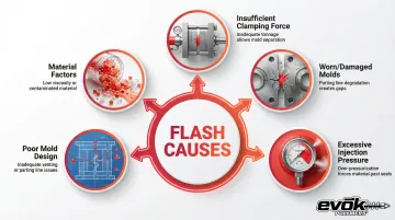
- Primary culprits: excessive injection pressure, poor mold design, wrong materials, and weak process controls
- Costs add up fast—material waste, 15-30 seconds deflashing per part, higher rejections, and returns
- Prevent flash through optimized mold design, controlled parameters, and regular maintenance
- Watch for gradual flash buildup, inconsistent part weights, and visible parting line gaps
What Is Flash in Injection Molding?
ASTM D3641 defines flash—also called flashing—as thin excess material that forms along parting lines, ejector pin locations, or other mold interfaces when molten plastic escapes during injection. While minor witness marks at parting lines are normal, excessive flash represents a defect requiring correction.
Flash severity varies significantly and impacts both part aesthetics and function:
- Barely visible lines: Thin witness marks at mold interfaces
- Moderate flash: Noticeable protrusions affecting appearance
- Severe flash: Thick excess material requiring manual removal
Industry quality standards typically classify flash as defective when it exceeds 0.05 mm for high-precision applications or 0.1 mm for standard components.
The defect appears as a thin, wafer-like protrusion that differs from burrs, which tend to be sharper and more localized. Understanding this distinction is critical for quality control and identifying the appropriate corrective measures.
Common Causes of Flash
Insufficient Clamping Force
When clamping tonnage falls below required levels, injection pressure forces mold halves apart, allowing plastic to escape at parting lines. The physics is straightforward: the minimum required clamp force equals the product of cavity pressure and the projected area of the part and runners.
This problem commonly occurs when:
- Molding larger parts without adequate machine capacity
- Using high injection pressures that exceed clamp force
- Press specifications don't match part requirements
The formula for required clamp force is: Required Clamp Force = Cavity Pressure × Projected Area
Industry guidelines suggest using a clamp factor of 2 to 8 tons per square inch depending on material type, with 3 tons/in² as a common baseline. Always include a safety factor (typically 1.2x) to account for process variations.
Worn or Damaged Molds
Repeated cycling causes progressive wear at parting lines, creating gaps where plastic escapes even with proper clamping force.
This wear is inevitable but accelerates when molds experience improper handling, corrosion, or inadequate maintenance schedules.
Parting line integrity deteriorates over time through:
- Mechanical wear from repeated opening and closing
- Plastic residue buildup preventing proper sealing
- Corrosion from moisture or aggressive materials
- Damage during mold changes or storage
Excessive Injection Pressure or Overpacking
Unnecessarily high injection or pack pressure forces excess material into any available gaps in the mold assembly.
Research shows that thin-wall applications requiring high-speed filling can demand nozzle pressures of 35,000 to 60,000 psi, significantly increasing the risk of blowing the clamp open.
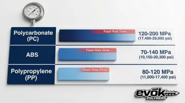
Typical pressure ranges where flash becomes problematic:
| Material | Pressure Range |
|---|---|
| Polycarbonate (PC) | 120–200 MPa (17,400–29,000 psi) |
| ABS | 70–140 MPa (10,150–20,300 psi) |
| Polypropylene (PP) | 80–120 MPa (11,600–17,400 psi) |
Overpacking during the hold phase is particularly problematic. If the cavity is overfilled or packed at excessive pressure, the internal force can exceed available clamp tonnage.
Poor Mold Design or Venting Issues
Improper parting line design, inadequate venting, or complex geometries create areas where mold halves don't seal properly. Venting issues trap air, preventing complete mold closure and creating pathways for flash formation.
Critical design factors include:
- Parting line geometry and sealing surface area
- Vent depth and location (standard depths: 0.02–0.05 mm)
- Gate placement and sizing
- Complex geometries that create uneven pressure distribution
Material-Related Factors
Low-viscosity materials with high Melt Flow Index (MFI) are more prone to flash because they seep through smaller gaps. Polypropylene (PP) and Polyethylene (PE) present higher flash risk than higher-viscosity resins like Polycarbonate (PC).
Hygroscopic resins require careful moisture control:
- Nylon (PA): Moisture content above 0.20% reduces viscosity, increasing flash tendency. Proper drying to <0.20% is essential.
- Polycarbonate (PC): Must be dried to <0.02% moisture to prevent degradation and flash.
Incorrect material temperature also alters flow characteristics. Excessive barrel or mold temperatures reduce material viscosity, increasing the likelihood of material escaping through microscopic gaps.
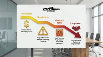
What Happens If Flash Is Ignored
Immediate Impacts
Flash creates direct financial losses through material waste, labor inefficiency, and scrap:
- Material waste: Excess plastic represents direct material loss, particularly costly with engineered resins
- Manual deflashing labor: Trimming and buffing can take 20 seconds per part in medical applications, significantly slowing production
- Higher rejection rates: Parts exceeding flash tolerances must be scrapped or reworked
Functional Consequences
Flash creates functional problems that extend far beyond appearance. Excess material prevents proper fit with mating components during assembly. It compromises gasket surfaces and O-ring grooves, leading to sealing failures. Flash also affects critical dimensions and creates sharp edges that can cut users or damage other components during handling.
Long-Term Effects
Ignoring flash creates escalating problems over time:
- Worsening mold damage: Flash indicates gaps that allow abrasive plastic to erode parting surfaces progressively
- Customer complaints: Quality issues damage relationships and reputation
- Lost business: Persistent quality problems lead to contract cancellations
Warning Signs You're About to Experience Flash
Catch flash issues early by monitoring for:
- Gradual parting line marks: Visible lines that grow thicker over successive production runs
- Inconsistent part weights: Variable material amounts indicate filling inconsistencies
- Mold closure difficulty: Trouble closing or locking the mold suggests alignment issues or buildup preventing proper seating
How to Prevent Flash
Optimize Mold Design and Maintenance
Proper parting line design starts with adequate sealing surfaces during initial mold development. This includes sufficient contact area and appropriate surface finish to ensure complete sealing under clamping pressure.
Implement regular mold inspection and maintenance:
- Daily/weekly cleaning of mold surfaces and vents
- Measurement of critical parting line dimensions
- Parting surface repair when wear exceeds tolerances
- Documentation of inspection findings and corrective actions
Working with injection molding specialists during design review helps identify potential flash risks before tooling is manufactured. Early collaboration on mold design prevents flash issues from developing during production.
Control Process Parameters
Once mold design is optimized, process control becomes your next line of defense. Establish optimal injection pressure, pack pressure, and hold time through scientific molding principles rather than trial-and-error.
Decoupled molding approaches fill the cavity to 95-98% using velocity control, then switch to pressure control for packing. This prevents the pressure spike that often causes flash.
Calculate minimum required clamping tonnage using this formula:
Required Tonnage = (Projected Area in in²) × (Clamp Factor in tons/in²) × Safety Factor
Where:
- Projected Area = the shadow area of all cavities plus runners
- Clamp Factor = 2-8 tons/in² depending on material (3 tons/in² is common baseline)
- Safety Factor = typically 1.2x to account for variations
Monitor and adjust clamping force to ensure adequate tonnage without over-clamping, which can damage molds or cause excessive wear.
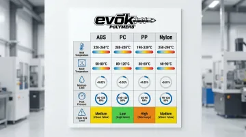
Select Appropriate Materials and Processing Conditions
Material selection directly impacts flash risk. Choose materials with viscosity characteristics suited to part geometry and mold design. Low-viscosity materials require tighter process control and potentially higher clamp tonnage.
Material processing guidelines:
| Material | Melt Temp (°C) | Mold Temp (°C) | Moisture Limit | Pack Pressure Guidance |
|---|---|---|---|---|
| ABS | 220-260 | 40-80 | <0.02% | 50-70% of injection pressure |
| PC | 280-320 | 80-120 | <0.02% | 50-70% of injection pressure |
| PP | 200-250 | 20-50 | N/A | Avoid overpacking |
| Nylon (PA) | 250-290 | 70-90 | <0.20% | Monitor cushion stability |
Maintain proper material drying protocols to ensure consistent flow properties. Document material specifications and processing windows for repeatability across production runs.
Verify Mold Condition and Alignment
Inspect parting lines regularly for wear, damage, or buildup that prevents proper sealing. Use precision measurement tools to verify that parting surfaces remain within tolerance.
Inspection protocol:
- Check for plastic residue or contamination on parting surfaces
- Measure parting line flatness and parallelism
- Verify vent depths remain within specification (0.02-0.05 mm)
- Inspect for corrosion or mechanical damage
Establish criteria for when mold repair or replacement is necessary. Generally, repair should be considered when parting line wear exceeds acceptable tolerances or when you cannot control flash through process adjustments alone.
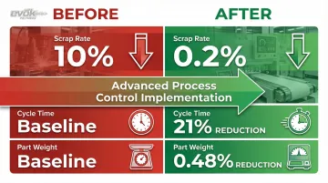
Implement Quality Control Monitoring
Use process monitoring systems to track injection pressure, clamping force, and cycle consistency. Cavity pressure sensors detect the exact moment the cavity fills, allowing precise switchover points that prevent overpacking and flash.
Establish inspection protocols that catch early flash development:
- Visual inspection of parting lines on sample parts each shift
- Dimensional measurement of flash-prone areas
- Part weight monitoring to detect filling variations
- Documentation with photos and measurements to identify patterns
Advanced process control has demonstrated the ability to reduce scrap rates from over 10% to less than 0.2% while simultaneously reducing cycle time by 21% and part weight by 0.48%.
Tips for Long-Term Prevention and Control
Establish preventive maintenance schedules for both molds and molding machines. Shot-based maintenance intervals provide systematic checkpoints:
Recommended PM schedule:
- 50,000 shots: Inspect for flash, wear, and drag marks; apply grease to moving components
- 150,000 shots: Check vent depths and widths against specifications; inspect hot runner manifolds
- 300,000 shots: Complete disassembly and cleaning; measure leader pins and bushings for wear
Build operator and technician expertise through:
- Training on early warning signs of flash development
- Proper troubleshooting procedure protocols
- Scientific molding curriculum from organizations like SPE and RJG
Document your processes systematically:
- Record optimal parameters for each part
- Track material specifications and lot variations
- Log historical flash issues with solutions applied
- Monitor when processes drift from optimal windows
Injection molding partners can help prevent flash before tooling is built. Evok Polymers specializes in design-phase optimization including mold flow analysis, gate and vent sizing, and process parameter development. This proactive approach addresses potential flash risks during design rather than after production tooling is manufactured.
Conclusion
Flash has identifiable root causes—primarily insufficient clamping force, worn molds, excessive pressure, and material factors. Each of these causes can be systematically addressed through proper engineering, process control, and maintenance practices.
Prevention through strategic design, process control, and maintenance is significantly more cost-effective than dealing with flash through deflashing and rework.
The investment in scientific molding principles, regular mold maintenance, and appropriate material selection delivers returns through:
- Reduced scrap rates
- Faster cycle times
- Improved part quality
- Lower production costs
Proactive measures and partnering with experienced injection molding partners can eliminate most flash issues while improving overall part quality and production efficiency.
By addressing flash prevention during the design phase and maintaining rigorous process control throughout production, manufacturers can achieve the tight tolerances required for modern injection molded components.
Frequently Asked Questions
What is flash injection?
Flash injection is an injection molding defect where excess plastic escapes at mold parting lines, creating thin unwanted protrusions that require removal through deflashing operations.
What causes flash in injection molding?
The two primary causes are insufficient clamping force allowing mold separation under injection pressure, and worn molds creating gaps at parting surfaces. Excessive injection or pack pressure compounds these issues by forcing material into gaps.
How do you fix flash in injection molding?
Start by verifying adequate clamping tonnage and inspecting mold condition at parting lines. Reduce injection and pack pressure if excessive, check material processing conditions, and make necessary mold adjustments to restore parting line integrity.
Can flash be completely eliminated?
Minor witness marks at parting lines are normal and acceptable in injection molding. However, excessive flash exceeding industry standards (0.05-0.1 mm) can be eliminated through proper mold design with adequate sealing surfaces, optimized process parameters, regular mold maintenance, and appropriate material selection and processing conditions.
How much does flash defect cost in production?
Flash costs include material waste, deflashing labor (15-30 seconds per part in precision applications), increased rejection rates, and potential customer returns. Advanced process control has reduced scrap rates from 10% to under 0.2% in documented cases.
When should I replace a mold that's causing flash?
Consider refurbishment when parting line wear causes uncontrollable flash and repair costs stay below 50-70% of new tooling. Complete replacement is necessary with catastrophic structural damage or when cooling system failures make refurbishment uneconomical.