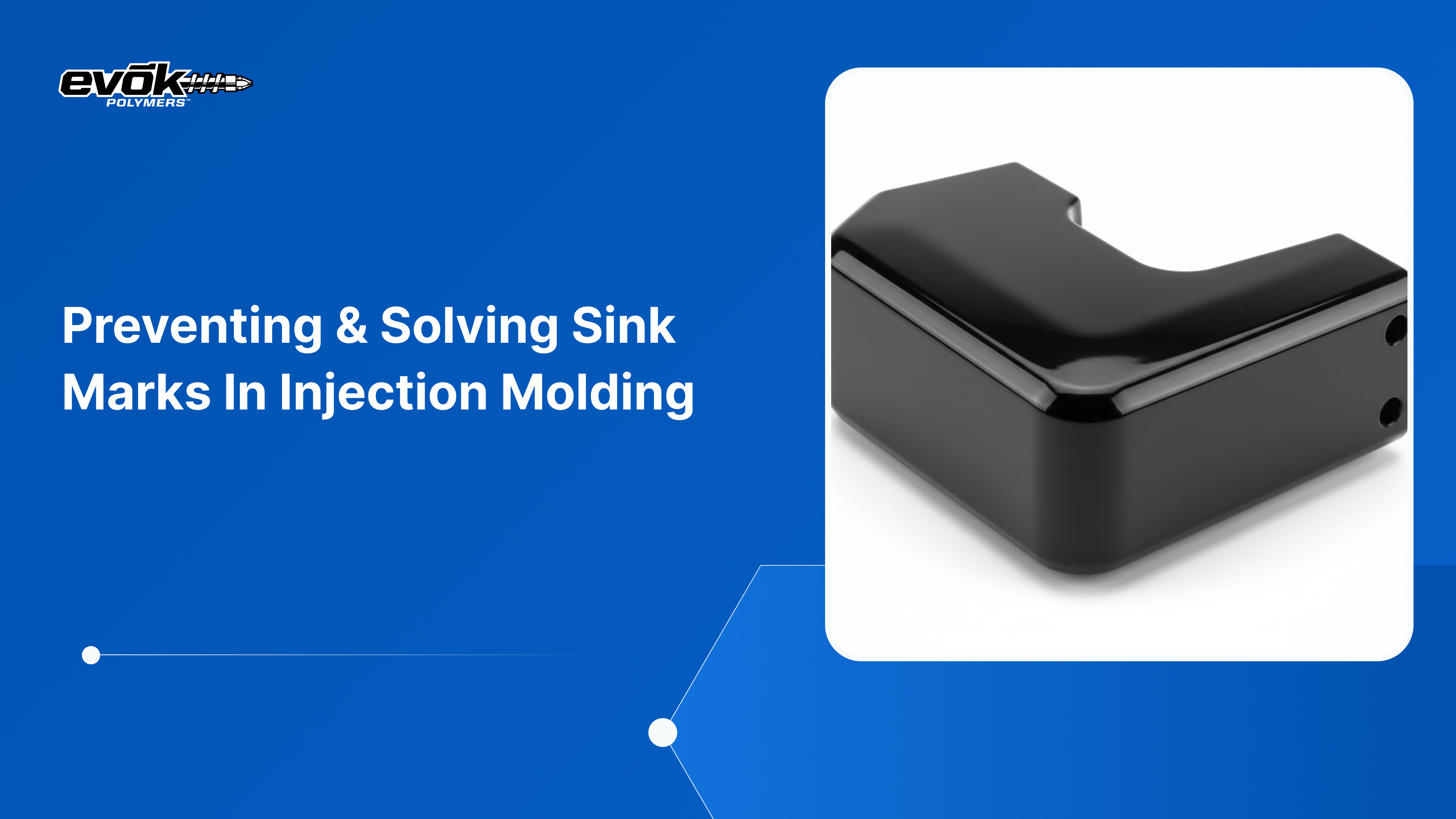
In high-volume plastic manufacturing, even small surface defects can turn into costly production issues. One of the most common and frustrating problems engineers face is sink mark injection molding.
These shallow depressions may look minor, but they often signal deeper issues within part design or processing conditions. Sink marks typically appear near thick sections such as ribs or bosses, where uneven cooling causes material to shrink inward.
In appearance-sensitive applications like automotive interiors or consumer electronics, even a single visible sink mark can lead to part rejection.
Understanding why sink marks form, and how to prevent them, requires a careful balance of design decisions, material behaviour, and process control.
Key Takeaways
To prevent injection moulding sink marks, internal features like ribs and bosses should typically be restricted to 40% to 60% of the thickness of the adjoining wall.
Proper packing and holding pressure (typically 50% to 80% of the initial injection pressure) is the most effective process-level tool for counteracting volumetric shrinkage.
Uniform cooling is critical; localized hot spots in the tool are a primary driver of sink, particularly in amorphous resins like ABS and Polycarbonate.
Placing the gate near the thickest section of the part allows the machine to pack the most volume-sensitive areas effectively before the gate freezes off.
Semi-crystalline materials like Polypropylene (PP) and Nylon (PA) exhibit higher shrinkage rates (up to 2%) compared to amorphous materials, making them naturally more prone to sinking.
What is a Sink Mark in Injection Molding?
To understand sink mark injection molding, it helps to look at what happens inside the mold during cooling. When molten plastic enters the cavity, the material touching the cold steel walls solidifies first, forming a rigid outer skin.
The plastic at the center remains hot and molten for longer. As this inner core cools, it naturally shrinks in volume, placing stress on the already solidified surface layer.
Problems arise in thick sections such as ribs, bosses, or intersections where material mass is higher. These areas cool more slowly and shrink unevenly. As the core contracts, it pulls inward on the outer skin.
If the surface cannot resist this force, it collapses slightly, creating a visible sink mark. In cases where the surface holds its shape, internal voids may form instead, reducing part strength.
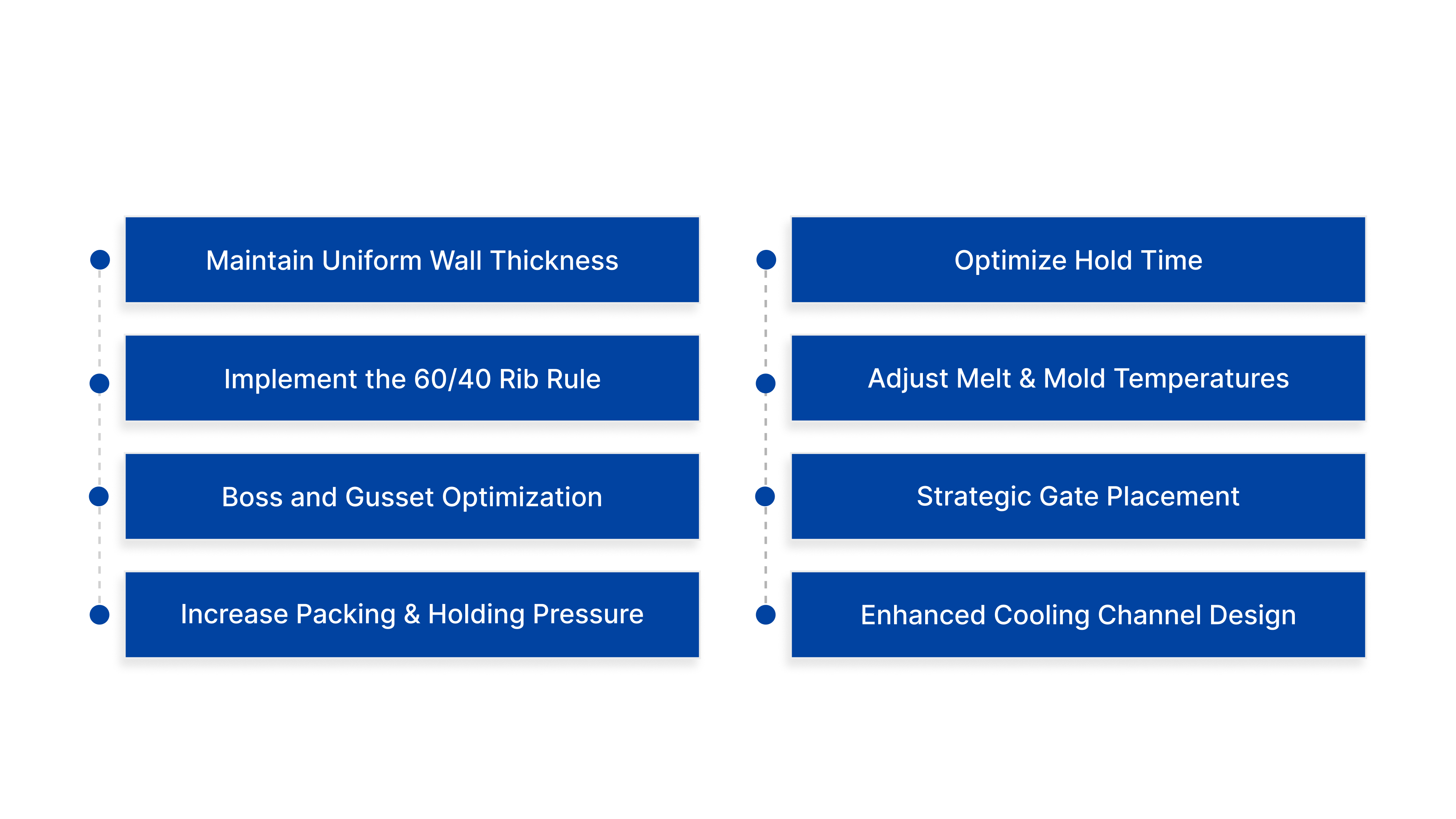
8 Most Effective Way to Prevent Sink Marks
The most effective way to address sink marks in injection molding is to eliminate their root cause during the CAD design stage. In most cases, part geometry plays a decisive role in whether sink defects appear.
1. Maintain Uniform Wall Thickness
The golden rule of injection molding is uniformity. Significant variations in wall thickness cause different areas of the part to cool at different rates. If a design requires a transition from a thin section to a thick section, engineers should use a gradual taper or coring out strategy to remove excess mass.
By keeping the nominal wall thickness consistent across the part, you ensure that the cooling rate is synchronized, minimizing the internal stresses that cause sink mark injection molding.
2. Implement the 60/40 Rib Rule
Ribs are essential for adding strength without adding unnecessary weight, but they are the most common cause of sink marks injection moulding. To avoid this, the thickness of the rib at its base should be no more than 50% to 60% of the thickness of the wall it is attached to.
In some high-gloss applications, this ratio may need to be as low as 30% to 40%. By keeping the rib thinner than the main wall, the rib will freeze first, preventing it from pulling material away from the cosmetic surface as it cools.
3. Boss and Gusset Optimization
Similar to ribs, bosses (cylindrical features used for fasteners) can create thick islands of plastic. A common technique to prevent injection molding sink marks around bosses is to use a relief or moat around the base of the boss. This reduces the local wall thickness and allows for more even cooling.
Additionally, using gussets (small triangular supports) instead of a single thick wall can provide the necessary rigidity while maintaining a thin, sink-resistant profile.
4. Increase Packing and Holding Pressure
This is the first line of defense on the factory floor. After the initial injection stage fills the mold to about 95-98%, the machine switches to packing and holding pressure. Increasing this pressure forces additional molten plastic into the cavity to fill the gaps created by shrinking material.
For most resins, the hold pressure should be set between 50% and 80% of the injection pressure. If the sink mark injection molding persists, it is often a sign that the pressure is not reaching the affected area.
5. Optimize Hold Time (The Gate Seal Test)
Pressure is only effective if the path to the part remains open. The gate is the small opening where plastic enters the mold cavity. If the hold time is too short, the material in the center of the part may still be molten when the pressure is released, allowing it to flow back out of the gate and cause a sink.
Operators should perform a gate seal study to determine exactly how long it takes for the gate to solidify. Extending the hold time until the gate is completely frozen ensures that the packing pressure has done its job.
6. Adjust Melt and Mold Temperatures
Temperature control is a delicate balance. If the melt temperature is too high, the plastic will be more fluid but will also shrink significantly more as it cools. Conversely, if the mold temperature is too low, the skin may freeze too quickly, blocking the flow of packing material to thick sections.
To solve injection moulding sink marks, it is often beneficial to lower the melt temperature slightly while ensuring the mold temperature is high enough to allow for a slow, controlled freeze of the surface.
7. Strategic Gate Placement
The location of the gate determines the pressure gradient within the mold. To prevent injection molding sink marks, the gate should always be positioned near the thickest section of the part. This allows the machine to apply the highest pressure directly to the area that will shrink the most.
If a part has multiple thick sections, a sequential gating system or multiple gates may be required to ensure that every hot spot receives adequate packing.
8. Enhanced Cooling Channel Design
Standard cooling channels are often drilled in straight lines, which can leave corners or thick sections uncooled. Modern toolmaking often employs conformal cooling, where 3D-printed metal inserts allow cooling channels to follow the exact contour of the part.
By bringing the coolant closer to the sink-prone areas, heat is removed more efficiently, allowing the surface to harden faster and resist the internal pull of the shrinking core.
The success of these mechanical and cooling adjustments is often dictated by the chemical properties of the resins being used.
Material Selection: How Resin Choice Influences Sink Mark Formation
The chemical structure of a polymer dictates its shrinkage profile. When selecting a material for a project where aesthetics are critical, engineers must account for how the resin will react inside the mold.
Amorphous vs. Semi-Crystalline Resins
Amorphous Resins (e.g., ABS, Polycarbonate, PS): These materials have a random molecular structure. They shrink less (typically 0.4% to 0.7%) and cool more uniformly. They are generally the safest choice for avoiding sink marks injection moulding.
Semi-Crystalline Resins (e.g., Polypropylene, Nylon, PE): These materials have a highly ordered structure that packs together as it cools. This results in much higher shrinkage rates (1.5% to 2.5%).
Because of this dramatic volume change, these materials are much more susceptible to injection moulding sink marks and require much more aggressive packing strategies.
The Role of Fillers and Additives
Adding fillers like glass fibers, carbon fibers, or minerals can significantly reduce the shrinkage of a material.
For example, a 30% glass-filled Nylon will shrink much less than pure Nylon. These fibers act as a physical internal skeleton that resists the inward pull of the shrinking polymer.
For parts where sink mark injection molding is a recurring problem, switching to a reinforced grade of the same resin is often a viable solution.
Conclusion
Preventing and solving sink mark injection molding issues is an essential skill for any engineering team aiming for a zero-defect production line.
By prioritizing uniform wall thickness, adhering to the 60/40 rib rule, and leveraging precise packing and holding pressures, manufacturers can significantly reduce scrap and improve the aesthetic appeal of their products.
As the industry continues to move toward more complex geometries and sustainable, high-shrinkage materials, the role of advanced simulation and AI-driven process control will only become more critical.
At Evok Polymers, we combine decades of practical experience with the latest 2026 manufacturing technologies to help our clients navigate these challenges.
We understand that a part is only as good as its surface finish, and we are committed to delivering parts that meet the most rigorous standards of the US market.
Ready to eliminate sink marks from your next production run? today.
Our engineering team is ready to conduct a comprehensive DFM and mold flow analysis to ensure your project is optimized for success from the very first shot.
Frequently Asked Questions (FAQs)
1. Can sink marks be completely eliminated in thick-walled parts?
While difficult, it is possible through a combination of gas-assisted injection molding or the use of chemical blowing agents. These techniques create internal pressure from within the molten core, pushing the plastic outward against the mold walls and neutralizing the pull of shrinkage.
This is a common solution for injection molding sink marks in handles and structural frames.
2. Is a sink mark always a sign of a structural failure?
Not necessarily. In many cases, a sink mark is purely a cosmetic defect. However, it does indicate an area of localized internal stress. If the part is subject to high mechanical loads or temperature fluctuations, the area under the sink mark injection molding blemish could become a point of crack initiation.
3. Why do I see sink marks even when my rib is 50% of the wall thickness?
This often happens if the material is a high-shrinkage semi-crystalline resin or if the radii (fillets) at the base of the rib are too large. While fillets are good for strength, they add extra mass to the junction. If the total mass at the junction exceeds the wall thickness, a sink will occur.
4. How does moisture in the resin affect sink marks?
Moisture creates steam during the heating process. This steam acts as a gas that can interfere with the packing phase, leading to inconsistent densities and localized injection moulding sink marks. Proper drying of hygroscopic materials like Nylon and PET is essential for surface quality.
5. What is the difference between a sink mark and a void?
A sink mark is a depression on the surface where the skin collapses. A void is a vacuum hole on the inside where the skin stays rigid, but the center pulls apart. Generally, you get a sink if the skin is hot or soft and a void if the skin is cold or hard. Both are caused by the same volumetric shrinkage issue.