Introduction
A single wall thickness miscalculation can derail an entire production run—causing sink marks across finished parts, warping that makes assembly impossible, or voids that compromise structural integrity. Wall thickness is the single most critical design parameter in injection molding, directly determining part quality, manufacturability, cycle time, and cost.
Approximately 40% of injection molding defects trace directly back to incorrect wall thickness decisions, resulting in sink marks, warpage, voids, and structural weak spots that compromise part performance.
Beyond defect prevention, wall thickness drives manufacturing economics exponentially, not linearly. Since cooling time represents roughly 80% of the total molding cycle, even modest thickness increases dramatically extend cycle times and inflate per-part costs.
Material consumption scales directly with thickness—a part with 0.120" walls uses 50% more resin than the same design at 0.080".
Getting wall thickness right from the start prevents costly redesigns and tooling modifications. This guide provides material-specific guidelines and design principles for optimizing wall thickness in custom injection-molded components.
Key Takeaways
- Wall thickness is the key design parameter for part quality, strength, cycle time, and manufacturing cost
- Uniformity prevents defects: stay within ±25% variation for amorphous polymers, ±15% for semi-crystalline materials
- Recommended ranges: 0.030"-0.125" for most thermoplastics, with 0.060"-0.080" offering the best balance of strength, cost, and cycle time
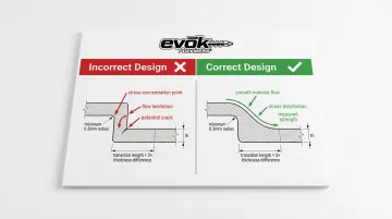
- Design gradual transitions using the 3:1 rule (transition length = 3× thickness difference) to ensure proper material flow
- Thicker walls drive exponential cost increases through material usage and dramatically longer cooling times
What Wall Thickness Represents in Injection Molding
Wall thickness defines the cross-sectional dimension of plastic material between two surfaces, serving as the structural foundation of every injection-molded part. According to ASTM D955-21 standards, wall thickness functions as the primary variable against which shrinkage and cooling behaviors are measured.
This single parameter simultaneously acts as:
- Design parameter — determines load-bearing capacity, impact resistance, and functional performance
- Manufacturing constraint — affects mold filling, material flow, and ejection forces
- Cost driver — impacts material volume, cycle time, and production throughput
These dimensions work together to create a complete part design. Nominal wall thickness represents the target baseline dimension assigned to the majority of the part's geometry. All secondary features—ribs, bosses, gussets, and mounting posts—are sized based on this baseline value.
Factors That Influence Optimal Wall Thickness
Multiple factors determine the optimal wall thickness for your part:
Part Functional Requirements: Structural loads, impact resistance needs, flexibility requirements, and operating environment conditions establish the minimum thickness threshold.
A housing for outdoor equipment requires different thickness than an interior cosmetic cover.
Material Selection: Different polymers exhibit vastly different flow characteristics and shrinkage rates. Liquid Crystal Polymers (LCP) can fill walls as thin as 0.010" due to extremely low melt viscosity, while Polycarbonate requires thicker sections or higher injection pressures to fill the same geometry.
Part Geometry and Size: Larger parts can support thinner walls relative to overall dimensions. Complex geometries with long flow paths may require thickness adjustments to ensure complete filling before material freeze-off.
Manufacturing Considerations: Flow length-to-thickness (L/T) ratios typically cap at 100:1 to 200:1 for standard materials, though specialized high-flow grades can achieve 400:1.
A 2mm wall thickness with a 100:1 ratio allows 200mm maximum flow length from the gate.
Economic Constraints: Material costs, cycle time targets, and production volume requirements create practical boundaries. High-volume production demands aggressive cycle time optimization, while low-volume runs may tolerate longer cycles to reduce tooling complexity.
Recommended Wall Thickness Ranges by Material
Each thermoplastic material possesses an optimal thickness range based on melt flow characteristics, crystalline structure, and shrinkage behavior.
These ranges represent practical moldability limits where parts can be manufactured consistently without excessive defects or processing difficulties.
Nominal Wall Thickness Guidelines by Material Type
| Material | Range (inch) | Range (mm) | Key Considerations |
|---|---|---|---|
| ABS | 0.045"-0.140" | 1.14-3.56 | Amorphous; good flow; low shrinkage |
| Acetal (POM) | 0.030"-0.120" | 0.76-3.05 | Crystalline; excellent flow; high shrinkage |
| Acrylic (PMMA) | 0.025"-0.500" | 0.64-12.7 | Amorphous; brittle; wide range |
| LCP | 0.030"-0.120" | 0.76-3.05 | Ultra-low viscosity; thin-wall capable |
| Nylon (PA) | 0.030"-0.115" | 0.76-2.92 | Crystalline; hygroscopic; high shrinkage |
| Polycarbonate (PC) | 0.040"-0.150" | 1.02-3.81 | Amorphous; high viscosity; tough |
| PBT/PET | 0.025"-0.125" | 0.64-3.18 | Crystalline; good flow; dimensional stability |
| HDPE | 0.030"-0.200" | 0.76-5.08 | Crystalline; excellent flow; high shrinkage |
| Polypropylene (PP) | 0.025"-0.150" | 0.64-3.81 | Crystalline; low density; high shrinkage |
| Polystyrene (PS) | 0.035"-0.150" | 0.89-3.81 | Amorphous; excellent flow; brittle |
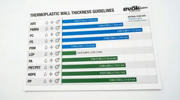
Source: Protolabs Wall Thickness Guidelines
These ranges balance moldability, strength, and economy. Parts can be molded outside these boundaries, but with increased difficulty, higher defect rates, and processing challenges.
Minimum Thickness Considerations
Practical minimum wall thickness for conventional molding ranges from 0.030"-0.040" (0.75-1.0mm) for most thermoplastics.
This lower limit ensures adequate material flow without excessive injection pressures or premature gate freeze-off.
Factors limiting minimum thickness:
- Flow length-to-thickness ratios max out at 150:1 to 200:1
- Thin walls require extreme pressures that can damage molds
- Gates solidify before cavity fills, causing short shots
Specialized thin-wall molding using high-speed injection presses and high-flow materials can achieve walls as thin as 0.010" (0.25mm). This requires specialized equipment, optimized tooling, and materials engineered for extreme shear rates.
Fiber-reinforced materials require thicker minimums, typically 0.050"+ (1.27mm+), to accommodate fiber length and prevent excessive fiber orientation that creates directional strength variations.
Maximum Thickness Considerations
On the opposite end of the spectrum, excessive wall thickness creates its own set of challenges.
Maximum practical wall thickness for conventional injection molding is 0.250" (6.35mm). Beyond this limit, parts suffer from:
- Excessive shrinkage and dimensional instability
- Extremely long cooling times
- Internal void formation as core shrinks
- High molded-in stress from differential cooling
Alternatives for thick-walled requirements:
Structural foam molding accommodates wall thicknesses from 0.157" (4mm) up to 0.500" (12.7mm) or more by injecting a foaming agent that creates a cellular core, eliminating sink marks while reducing part weight.
Gas-assist injection molding injects pressurized gas into the melt stream to core out thick sections from the inside, preventing sink marks and reducing material usage.
Compression molding offers an alternative process for extremely thick-walled parts where injection molding becomes impractical.
Crystalline vs. amorphous sensitivity:
Semi-crystalline materials (PP, PE, Nylon, Acetal) exhibit higher shrinkage rates than amorphous materials (ABS, PC, PS) due to crystalline structure formation during cooling. Thick sections in crystalline materials are particularly prone to warpage and dimensional instability.
Key Design Principles for Wall Thickness Optimization
Industry best practices for wall thickness design prevent defects, reduce manufacturing costs, and ensure consistent part quality across production runs.
Maintain Uniform Wall Thickness Throughout the Part
The 25% uniformity rule represents the gold standard for wall thickness design:
- Amorphous polymers (ABS, PC, PS): Maintain all wall sections within ±25% of nominal thickness
- Semi-crystalline polymers (Nylon, PP, PBT): Tighten tolerance to ±15% of nominal thickness due to higher shrinkage rates
Source: DFM Injection Molding Guidelines
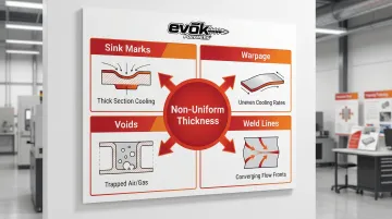
Non-uniform walls create multiple defect modes:
- Thick sections shrink more than thin sections, creating internal stress and warpage
- Molten plastic races through thick sections while stalling in thin areas, causing incomplete fill and weld lines
- Thick sections pull inward as the core solidifies last, creating visible sink marks on surfaces
- When the skin resists sinking, internal shrinkage creates vacuum voids that compromise strength
Achieve uniformity through strategic design choices:
- Core out thick sections to maintain consistent wall thickness
- Add ribs for reinforcement instead of increasing wall thickness
- Use uniform shell design with external features rather than internal mass
Use Gradual Transitions Between Thickness Changes
The 3:1 transition rule: When thickness changes are unavoidable, the transition length should be at least 3 times the thickness difference.
Example: Transitioning from 2mm to 3mm (1mm difference) requires a minimum 3mm transition length.
Abrupt transitions create three critical problems:
- Flow stalls in thin sections while racing through thick sections, creating unbalanced filling
- Material flows around the perimeter faster than through the center, trapping air
- Sharp steps create weak points prone to crack initiation under load
Use chamfers or tapers rather than sharp steps. Generous radii (minimum 0.5× wall thickness) at corners reduce stress concentration factors and improve material flow.
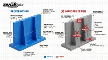
Follow Rib Design Guidelines Proportional to Nominal Wall
Ribs provide structural stiffness without the penalties of thick walls, but improper sizing causes visible sink marks on the opposite surface.
Rib thickness: 50-70% of nominal wall thickness prevents sink marks on Class A surfaces. For high-gloss appearance parts, reduce to 30% to eliminate any surface depression.
Rib height: Should not exceed 2.5-3.0× nominal wall thickness. Taller ribs become difficult to fill and eject, requiring excessive draft angles.
Rib spacing: Space ribs at least 2-3× nominal wall thickness apart to prevent heat from trapping between features, which extends cooling time.
Critical dimensions for proper rib performance:
- Draft angles: 0.5-1.5° per side for easy ejection
- Base radius: 0.25-0.40× nominal wall thickness for smooth stress distribution
- Corner radius: 0.5× wall thickness minimum to reduce stress concentration
Design for Consistent Cooling and Minimal Stress
Uniform wall thickness creates uniform cooling rates, which minimizes molded-in stress and warpage tendency.
Thick sections cool from outside-in, creating internal stress and potential voids as the core solidifies last. Thin sections cool rapidly and uniformly, reducing differential shrinkage.
Design target: The thickest section should cool in less than twice the time of the thinnest section to maintain dimensional stability and minimize internal stress.
How Wall Thickness Affects Manufacturing Economics
Wall thickness impacts part cost exponentially through both material consumption and cycle time. Understanding this relationship enables informed design decisions that balance performance with economic reality.
Material Cost Impact
Material costs typically represent 30-60% of total part cost, making thickness reduction a primary cost-saving opportunity. The relationship is direct and linear:
- A part with 0.120" walls uses 50% more material than the same part with 0.080" walls
- Reducing wall thickness from 0.100" to 0.080" cuts material volume by 20%
For high-volume production runs, even small thickness reductions generate substantial material savings that compound across millions of parts.
Cycle Time and Production Cost Impact
Cooling time increases with the square of wall thickness, following the relationship:
Cooling time ∝ (wall thickness)²
This quadratic relationship means:
- Doubling wall thickness quadruples cooling time
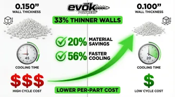
- Reducing thickness from 0.150" to 0.100" (33% reduction) cuts cooling time by approximately 55%
Since cooling represents roughly 80% of the total molding cycle, thickness optimization delivers disproportionate cycle time savings. Cycle time typically represents 40-70% of part cost through machine time, labor, and overhead allocation.
Consider a practical scenario: A part with 0.150" walls requires approximately 45 seconds cooling time. Reducing to 0.100" walls drops cooling time to roughly 20 seconds—a 56% reduction that dramatically increases throughput and lowers per-part cost.
Tooling and Quality Considerations
Beyond cycle economics, wall thickness drives tooling requirements. Thicker walls require:
- Higher tonnage injection presses to generate sufficient clamping force
- Larger shot sizes and more robust plasticizing units
- More extensive mold cooling systems with larger cooling lines
These requirements increase tooling costs and limit machine availability.
Parts designed within optimal thickness ranges have wider processing windows, reducing scrap rates and quality issues during production.
Common Wall Thickness Design Mistakes to Avoid
These common design mistakes lead to costly mold modifications, quality issues, and extended cycle times. Identifying them during early Design for Manufacturability (DFM) analysis prevents expensive corrections after tooling begins.
Designing Thick Sections Without Coring Strategy
The mistake: Solid thick sections—bosses, mounting posts, rib intersections—that are 2-3× the nominal wall thickness.
Consequences:
- Sink marks appear as surface depressions opposite thick sections where internal shrinkage pulls the skin inward
- Vacuum cavities form internally when the rigid skin prevents surface sinking
- Cooling time increases exponentially with section thickness
- Warpage: Differential shrinkage between thick and thin areas creates dimensional instability
Solution: Core out thick sections to maintain uniform walls. Use ribs for reinforcement rather than solid mass. Redesign geometry to distribute material evenly rather than concentrating it in localized areas.
Sharp transitions create equally serious problems.
Abrupt Thickness Transitions and Sharp Corners
The mistake: Sudden steps from thin to thick sections, or sharp internal corners with zero radius.
Consequences:
- Stress concentrations — Sharp transitions act as crack initiation points, reducing impact strength and fatigue life
- Flow hesitation — Material flows more readily through thick sections, causing thin areas to freeze off prematurely
- Weld lines — Flow fronts that hesitate and rejoin create weak lines prone to failure
Solution: Apply the 3:1 transition rule with gradual tapers. Use generous radii (minimum 0.5mm) at all corners. Design chamfered transitions rather than sharp steps.
Material selection directly impacts acceptable thickness variation.
Ignoring Material-Specific Thickness Requirements
The mistake: Applying generic thickness guidelines without considering specific material characteristics—crystalline vs. amorphous structure, filled vs. unfilled grades.
Consequences: Crystalline materials (PP, Nylon, Acetal) exhibit higher shrinkage and narrower thickness tolerance than amorphous materials (ABS, PC). A thickness variation acceptable for ABS may cause severe warpage in Nylon. Glass-filled materials require thicker minimum walls to accommodate fiber length and prevent excessive fiber orientation that creates directional properties.
Solution: Material selection and wall thickness optimization must happen simultaneously, not sequentially. Work with experienced injection molders who perform mold flow analysis before tooling begins. Evok Polymers integrates material considerations into early-stage design collaboration, identifying material-specific thickness issues before mold construction.
Frequently Asked Questions
How do you decide the wall thickness of a plastic part?
Start with minimum thickness needed for structural requirements, verify it falls within material flow capabilities, maintain uniform thickness (±25% for amorphous, ±15% for crystalline), and validate with mold flow analysis before finalizing.
What is the recommended wall thickness for injection molding?
General recommendation is 0.030"-0.125" for most thermoplastics, with 0.060"-0.080" representing optimal balance. Specific ranges vary by material—LCP can go as thin as 0.030", while structural parts may require 0.120"+.
What is the minimum wall thickness for PBT?
Minimum practical wall thickness for PBT (polybutylene terephthalate) is 0.030" (0.75mm), with optimal range 0.030"-0.120". As a semi-crystalline material, PBT requires uniform thickness design to prevent warpage from shrinkage.
What is the minimum wall thickness for nylon?
Minimum practical wall thickness for Nylon (PA) is 0.030" (0.75mm), with optimal range 0.030"-0.115". High shrinkage rates (0.7-3.0%) require strict thickness control for dimensional stability.
What is the maximum wall thickness for injection molding?
Maximum practical thickness is 0.250" (6.35mm) for conventional injection molding. Thicker sections require excessive cycle times and are prone to sink marks and internal voids. For thick-walled needs, consider structural foam molding (0.157"-0.500") or gas-assist molding.
How does wall thickness variation affect part quality?
Thickness variations exceeding 25% (15% for crystalline materials) cause differential cooling that leads to warpage, internal stress, sink marks, and unpredictable shrinkage. Uniform thickness is the most effective strategy for preventing defects.
Ready to optimize your part design for injection molding success? Evok Polymers has optimized wall thickness and material selection for custom parts across industries from medical devices to powersports for 25 years. Contact us at 612-991-2001 to discuss how proper wall thickness design can reduce your manufacturing costs while improving part quality.