
Introduction
A gate is a small opening — but it's doing a lot of work. Where molten plastic enters the mold cavity, the gate controls fill quality, part cosmetics, cycle time, and tool longevity. It's also the smallest cross-sectional area in the entire flow path, which means extreme shear rates and pressure drops concentrate right there.
While gate sizing might appear to follow simple rules of thumb, real-world results vary widely based on material viscosity, part geometry, gate type, and downstream processing requirements. Getting it wrong is expensive to fix once steel is cut. Tooling rework costs range from 15% to 40% of a new mold's price and adds 1 to 3 weeks of downtime.
This article covers the sizing process, the variables that control outcomes, and the mistakes that derail otherwise well-designed parts.
Key Takeaways
- Gate depth depends on wall thickness and material viscosity; sizing conservatively first reduces rework risk
- Gate width controls material flow speed and must account for shear rate, part volume, and cavity count
- Undersized or oversized gates cause sink, jetting, burn marks, voids, and warp—all avoidable with upfront analysis
- Using mold flow simulation before cutting steel is the most reliable way to validate gate sizing decisions
Why Gate Sizing Matters More Than You Think
Why Gate Sizing Has an Outsized Impact on Part Quality
The gate is the transition zone between the runner system and the cavity. Because it represents the smallest cross-sectional area in the flow path, shear rate, pressure drop, and material behavior are most extreme at this point. A small change in gate radius or thickness has a disproportionate effect on the shear the material experiences.
Downstream consequences of improper gate sizing include:
- Too shallow: freezes prematurely, causing underpacking that leads to sink marks, voids, warp, and dimensional inconsistency
- Too deep: extends packing time unnecessarily, increases cycle time, and risks material backflow into the runner
- Too narrow: forces material through at excessive velocity (sometimes exceeding 160 mph), causing burn marks, jetting, and material degradation
Gate decisions made early in design save money throughout the program. At Evok, steel-safe gate sizing is built into every initial tool design as standard practice — intentionally sizing gates on the conservative side so they can be opened by removing steel if needed, rather than requiring costly weld repair that compromises tool integrity down the line.
How to Size an Injection Molding Gate: Step by Step
Step 1: Identify the Material and Its Viscosity Class
Classify the resin as low-viscosity (e.g., polyethylene, nylon), medium-viscosity (e.g., polypropylene, acetal), or high-viscosity/shear-sensitive (e.g., polycarbonate, rigid PVC, acrylic). This classification drives both gate depth and gate width calculations.
Important: Melt Flow Index (MFI) alone is not a reliable viscosity guide. MFI tests operate at low shear rates (around 20 s⁻¹) that don't reflect polymer behavior at injection molding gate conditions (>1,000,000 s⁻¹). Two resins with identical MFI ratings can behave very differently under real injection conditions. Use capillary rheometry or established industry experience instead.
Step 2: Determine Gate Depth
Gate depth controls freeze-off time and is directly linked to nominal wall thickness at the gate location. Use these rule-of-thumb depth percentages by viscosity class:
- Low-viscosity resins (PE, PP, Nylon): 40–50% of wall thickness
- Medium-viscosity resins (POM, ABS): 50–60% of wall thickness
- High-viscosity or shear-sensitive materials (PC, PMMA, rigid PVC): 60–75% of wall thickness
Use the lower end for thin walls and the higher end for thick walls. Always start gate depth on the shallow (steel-safe) side—shallow gates can be opened up; a gate that is too deep requires weld repair.
Step 3: Determine Gate Width
Gate width controls material flow speed through the gate and must be sized based on how much material needs to enter the cavity and how fast. A narrower gate increases shear velocity, which can cause burning or jetting. An overly wide gate slows flow enough that premature freeze-off may occur, especially in thin-walled parts.
Industry formula for initial gate width:
W = n × √A / 30
Where W is gate width in inches, A is cavity surface area in square inches, and n is a material constant:
- n = 0.6: Free-flowing materials (PE, PS)
- n = 0.7: Slightly more viscous materials (PP, Acetal, PC)
- n = 0.8: PMMA, Nylon, Cellulose acetate
- n = 0.9: Highly viscous materials (Rigid PVC)
This formula is a conservative starting point — actual width may need adjustment based on flow analysis. In multi-cavity molds, volumetric flow rate per cavity drops with each runner branch, so gate width requirements decrease as cavity count increases. Ignoring this relationship leads to oversized gates and extended cycle times.

Step 4: Set Gate Land Length
Once gate depth and width are set, land length is the final geometric variable to dial in. Gate land — the short straight section between the gate taper and the cavity — controls pressure drop and affects vestige appearance on the finished part. Land that is too long adds pressure drop without benefit and can cause burn marks or flow lines.
General guideline: Gate land should be approximately half the gate depth but should not exceed 0.030 inches (0.75 mm) for most applications. Keep land as short as practically possible for the mold design.
Key Variables That Affect Gate Sizing Outcomes
Gate sizing is shaped by multiple interacting variables, and getting any one of them wrong compounds into defects, rework, or a gate that needs to be cut again. The four variables below cover where most sizing errors originate.
Material Shear Sensitivity
Resin type sets the baseline for how large a gate needs to be:
- Amorphous resins (PC, PMMA, rigid PVC), fiber-reinforced grades, and heavily filled compounds need larger gates to prevent temperature rise, fiber breakage, and surface defects. Fiber-filled resins typically require gates approximately 10% larger than an equivalent unfilled grade.
- Semi-crystalline, unfilled resins (PP, PE, nylon) tolerate smaller gates and higher shear rates without cosmetic or property degradation.
Part Wall Thickness and Geometry
Wall thickness at the gate location drives gate depth. The gate must stay open long enough for the part to pack out before freeze-off—thicker parts need deeper gates, and irregular wall transitions near the gate create inconsistent freeze timing and packing pressure.
Flow length from gate to end-of-fill determines gate width. Longer flow paths need more gate width to avoid excessive pressure drop across a restrictive gate.
Cavity Count and Flow Rate per Gate
In single-cavity tools, the full machine flow rate passes through one gate. In multi-cavity molds, flow splits at each runner branch—the volumetric flow rate per gate drops proportionally. Gate width must be sized to that per-cavity flow, not the total shot volume.
Packing Stage Requirements
The gate must remain open for the full duration required to pack the part. A gate that freezes before the part is fully packed results in sink, internal voids, warpage, and dimensional inconsistencies. Packing time sets the minimum gate cross-section—gate freeze-off is a design constraint, not a variable to optimize away.

Common Gate Types and How Sizing Differs
Gate geometry varies significantly by type, and sizing rules shift with each one. Here's how the three most common categories compare.
Edge Gate
Edge gates offer the widest sizing flexibility of any gate style. Because they sit along the parting line, they can accommodate larger cross-sections without the mechanical constraints that limit other types.
- Sized at 50–80% of the injected wall thickness
- Supports better packing control and lower shear rates than most alternatives
- Requires secondary gate removal after ejection
- Gate scar is visible on the part edge — factor this into cosmetic requirements
Tunnel (Sub) Gate
Tunnel gates automate degating during ejection, which saves post-processing time. That convenience comes with a tighter sizing window.
- Also sized at 50–80% of the wall it sits on, but the upper limit is critical
- A gate that is too large risks breakage failure during ejection rather than clean separation
- Generally smaller than edge gates in absolute terms
- Not well-suited for large, thick, or shear-sensitive parts due to size constraints
Fan, Film, and Diaphragm Gates
These gates distribute flow across a wide area — common in flat, thin-walled, or optically sensitive parts. Standard percentage-based sizing rules don't apply cleanly here.
- Gate width is inherently large, but depth is the critical sizing variable
- Insufficient depth causes premature freeze-off across the flow area
- Wider flow area reduces material velocity, requiring added depth to sustain pack pressure
- Often run deeper than percentage guidelines suggest — this is expected, not a deviation
Common Gate Sizing Mistakes and How to Avoid Them
Most gate sizing problems trace back to four repeatable errors — each preventable with the right approach upfront.
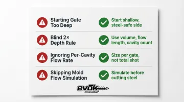
Starting gate depth too deep. Always begin on the steel-safe (shallow) side. A gate that's too deep requires costly weld repair to fix; a shallow gate can be opened quickly. DFM partners like Evok build steel-safe depth into initial tool designs as standard practice.
Applying the "gate width = 2× gate depth" rule blindly. This rule ignores part volume, flow length, cavity count, and material shear rate. In high-shear-rate scenarios, a gate that's too narrow can push material through at over 100 mph — causing burn marks and jetting.
Ignoring per-cavity flow rate in multi-cavity molds. In a 16- or 32-cavity mold, each gate handles only a fraction of total machine flow. Sizing gates against total shot volume produces oversized gates, extended cycle times, and packing failures.
Skipping mold flow simulation. Trial-and-error sampling without simulation adds unnecessary tooling modification cycles. Simulation confirms gate dimensions, freeze timing, and packing adequacy before any steel is cut.
Troubleshooting Gate-Related Defects
Gate-related defects are among the most common in injection molding — and the most misdiagnosed. Most trace back to gate depth, width, land length, or location rather than process parameters alone. Here's how to diagnose the three defects that show up most often.
Sink Marks and Internal Voids Near the Gate
The gate is likely freezing prematurely, cutting off packing pressure before the part fully solidifies. A gate land that's too long can compound this by creating excessive pressure drop.
To diagnose and fix:
- Confirm gate depth is adequate for the wall thickness and material class
- Shorten gate land length if it exceeds recommended maximums
- Verify holding pressure timing relative to gate freeze-off
Jetting or Burn Marks at the Gate
A gate that's too small — in depth or width — forces material into the cavity at excessive velocity and temperature. Reducing injection speed to compensate is a common mistake; it trades one defect for reduced fill quality elsewhere.
The right fix is to increase gate area directly:
- Increase gate width first — depth is constrained by wall thickness
- A larger gate cross-section drops material velocity without touching injection speed settings
Flow Lines or Blush Immediately Inside the Gate
An oversized gate land creates a hesitation zone where material velocity drops sharply as it enters the open cavity. A gate that's too shallow for the material's viscosity produces the same result.
Two adjustments typically resolve this:
- Shorten gate land to the recommended maximum for the material class
- Verify gate depth aligns with the viscosity guidelines for your resin
Frequently Asked Questions
What are common injection molding gate sizes?
Gate dimensions vary widely by application. Edge gates are commonly 50–80% of wall thickness in depth, with width ranging from equal to the depth (small parts) to several times the depth (large parts). Tunnel gates are typically 0.5–3 mm in diameter depending on wall thickness and resin.
How do you calculate injection molding gate size?
Gate depth is typically 40–75% of nominal wall thickness, depending on material viscosity. Gate width can be estimated with the formula W = n × √A / 30, where n is a material constant and A is cavity surface area. Verify both with mold flow simulation before finalizing tooling.
What happens if a gate is too small in injection molding?
Excessive shear rate causes burn marks, jetting, and material degradation. Insufficient pack pressure causes sink, voids, warpage, and dimensional inconsistency. Injection pressure increases and processing window narrows.
What is gate land length and why does it matter?
Gate land—the short straight section between the gate taper and the cavity—should be approximately half the gate depth and never exceed 0.030 inches. Excess land length increases pressure drop and causes flow lines and burn marks.
How does material type affect gate sizing?
High-viscosity or shear-sensitive materials (PC, acrylic, rigid PVC) require larger gates to manage pressure and shear. Fiber-filled resins need approximately 10% larger gates than unfilled equivalents. Low-viscosity resins (PE, nylon) can use smaller gates with higher shear rates without part quality degradation.
When should you use a tunnel gate vs. an edge gate?
Tunnel gates are preferred when automatic degating is required, eliminating secondary trimming operations. Edge gates are better suited for large parts, shear-sensitive materials, or applications requiring maximum packing control, since they support larger cross-sections than tunnel gates can achieve within ejection constraints.