In plastic manufacturing, small design choices can have an outsized impact on final part quality and production efficiency. One of the most important of these is the injection molding gate, the point where molten plastic enters the mold cavity.
Its size, shape, and location influence how the material flows, cools, and solidifies, directly affecting strength, surface finish, and cycle time.
For product engineers and manufacturing teams, choosing the right injection molding gate is a practical decision that weighs performance, tooling design, and production costs.
Getting this right early helps avoid defects, rework, and unnecessary complexity during high-volume manufacturing.
Key Takeaways
Every gate leaves a remnant of material known as a vestige; choosing the right gate type determines whether this mark is visible or hidden.
Gates regulate the velocity of the molten plastic, preventing material degradation caused by excessive friction and heat.
Automatic degating systems eliminate the need for manual trimming, which is a major cost-saving factor in US-based manufacturing.
Proper gate placement ensures the cavity fills from thick to thin sections, reducing internal stresses and preventing defects like sink marks.
The gate acts as a valve that must freeze at the precise moment to prevent backflow and maintain consistent part weight.
The Fundamental Function of an Injection Molding Gate
To understand the diversity of gates in injection moulding, one must first understand their physical role within the process. A gate is essentially a restrictor.
As the injection molding machine pushes the molten polymer through the sprue and runners, the gate serves as the final entry point. Its primary job is to provide enough pressure to fill the cavity completely while ensuring that the melt front moves steadily to avoid air entrapment.
Beyond filling, the gate performs a vital thermal function. Once the cavity is full, the machine maintains holding pressure to compensate for material shrinkage as the part cools. The gate is designed to freeze before the runner does.
This ensures that the material inside the part stays put, preventing it from being sucked back out into the runner system. If the gate is sized incorrectly, the part may suffer from inconsistent dimensions or structural weaknesses.
With the basic mechanical purpose established, we can look at the two primary methods of removing these gates after the part is formed.
Manual Trim vs. Automatic Trimming Systems
One of the first decisions an engineer must make when selecting injection molding gates is whether the gate will be removed manually or automatically. This choice has a direct impact on the initial cost of the mold and the long-term cost of each part produced.
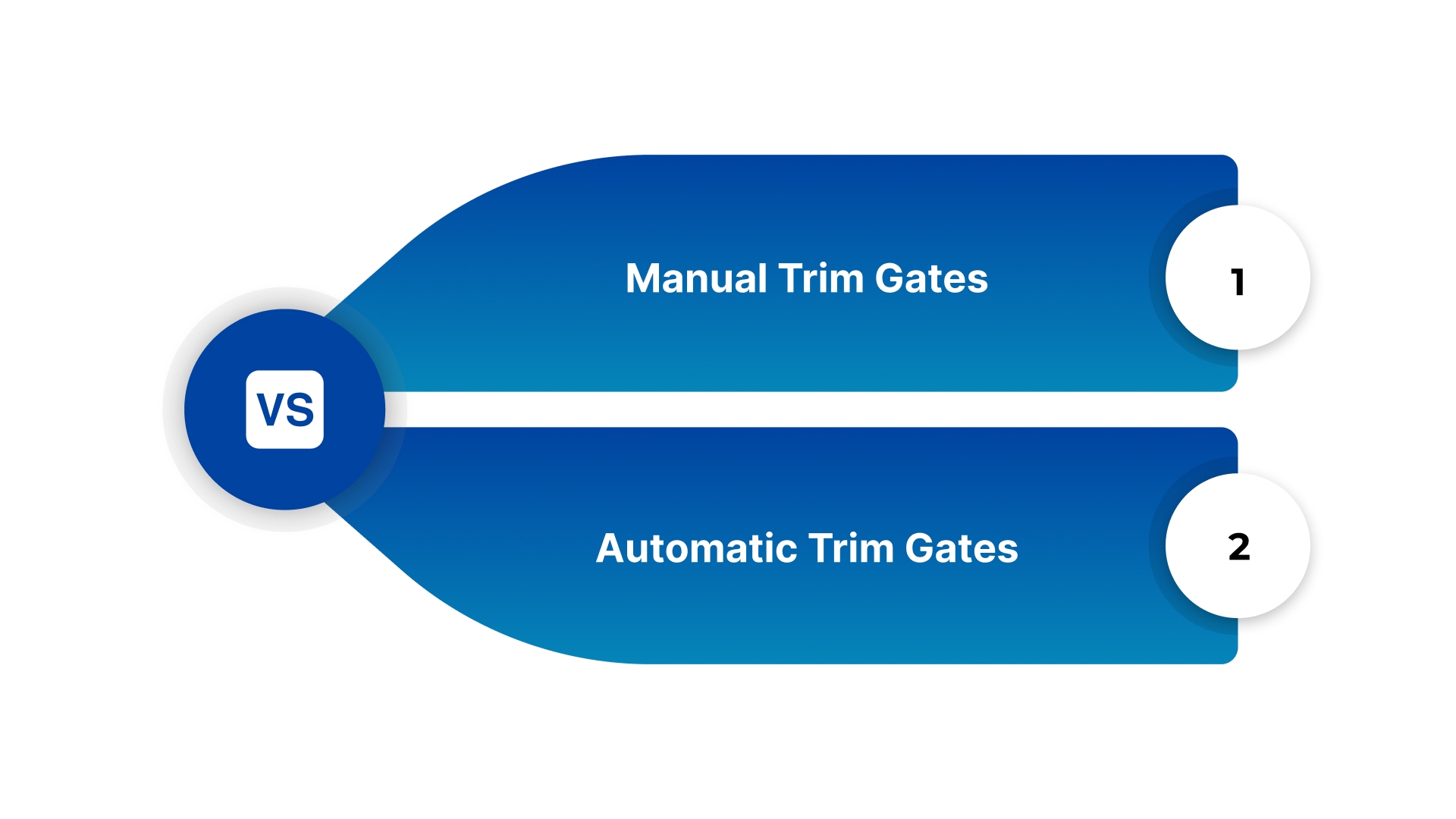
Manual Trim Gates
Manual gates are typically simpler to design and machine into the mold. These include edge gates, fan gates, and tab gates. Because they are located on the parting line, the part and the runner system are ejected together as a single unit.
An operator or a robot must then use nippers or a trimming fixture to separate the part from the runner. While the tooling is more affordable, the added labor cost makes these gates less ideal for extremely high-volume runs where seconds and cents matter.
Automatic Trim Gates
Automatic gates are engineered to shear or break away from the part during the ejection phase. Submarine gates, pin gates, and cashew gates fall into this category. The shearing action is triggered by the movement of the mold plates or the action of the ejector pins.
This eliminates secondary labor, making them the standard for automated production facilities in North America.
However, these systems require higher precision in mold manufacturing and can be more difficult to maintain over hundreds of thousands of cycles.
Understanding the difference between manual and automatic systems provides the context needed to evaluate specific gate geometries.
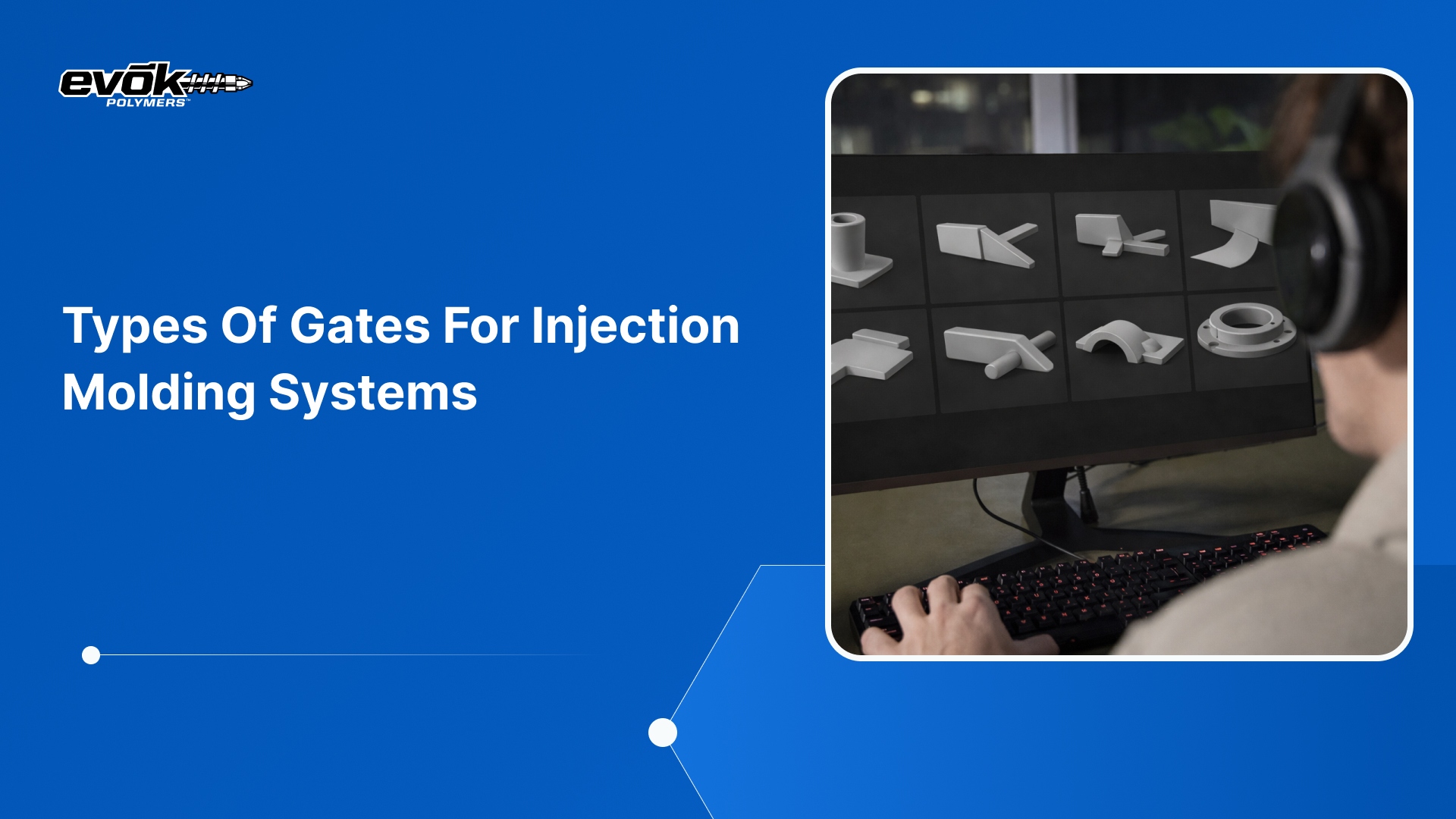
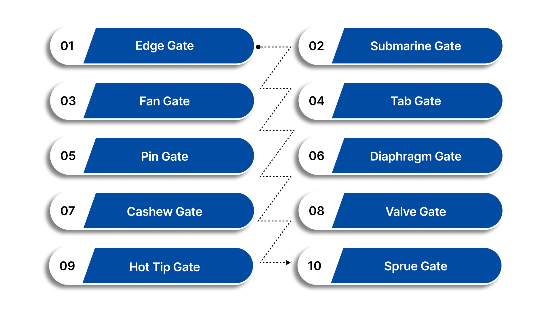
10 Essential Types of Injection Molding Gates
The variety of available gates allows engineers to tailor the injection process to the specific needs of the part. Below are the ten most common types of gates used in modern manufacturing.
1. Edge Gate
The edge gate is the most common and straightforward injection molding gate used in the industry today. As the name suggests, it is located on the edge or parting line of the mold.
Because it is simple to machine and modify, it is frequently the first choice for prototypes and standard industrial parts.
Advantages and Applications
Edge gates are versatile and can be used with almost any material. They allow for a large volume of plastic to enter the cavity quickly, making them ideal for larger components.
However, they require manual degating, meaning an operator or a robotic arm must trim the part from the runner after it is ejected.
This leaves a visible vestige on the side of the part, which may require secondary finishing if the part is a cosmetic component.
Limitations
The thickness of an edge gate is typically between 50% and 80% of the part's wall thickness. If the gate is too thin, the plastic may cool too early, causing short shots. If it is too thick, the removal process can damage the part.
Engineers often favor this gate because it allows for easy adjustments to the flow rate even after the mold has been initially fabricated.
With the reliability of edge gates established, projects requiring high-volume automation often move toward self-shearing designs.
2. Submarine (Tunnel) Gate
The submarine gate, often called a tunnel gate, is a favorite for high-volume automated production. It is machined at an angle through the mold steel so that it enters the cavity below the parting line.
Advantages
The primary benefit of this injection molding gate is that it is self-degating. As the mold opens and the part is ejected, the sharp edge of the gate tunnel shears the plastic away from the part.
This eliminates the need for manual trimming, reducing labor costs and cycle times. It is commonly used for small parts where manual labor would be inefficient.
Limitations
Submarine gates are generally limited to smaller parts and materials that are flexible enough to shear without cracking. Brittle resins like highly glass-filled nylons may snap unevenly, leaving a messy vestige or causing gate blush near the entry point.
The angle and size of the tunnel are critical to ensuring the gate breaks cleanly without leaving fragments inside the mold.
For parts that need a very clean surface on the edge but still require automation, the fan gate provides an alternative solution.
3. Fan Gate
A fan gate is a wide, thin gate that gradually widens from the runner to the cavity. This fan shape helps to distribute the molten plastic across a wider area as it enters the mold.
Advantages
The widening geometry of a fan gate reduces the velocity of the plastic, which in turn reduces shear stress. This is particularly useful for flat, thin parts like smartphone cases or tablet covers, where warpage and jetting are major concerns.
By spreading the flow, the fan gate ensures a more uniform melt front, leading to a part with fewer internal stresses.
Limitations
Like the edge gate, the fan gate is located on the parting line and requires manual removal. Because it is much wider than a standard edge gate, the vestige is more prominent and often requires a clean-up operation with a knife or fixture.
Despite the extra labor, the structural benefits for flat parts often outweigh the cosmetic drawbacks.
If the part geometry makes an edge-style entry impossible, engineers often look toward the center of the part for gate placement.
4. Tab Gate
A tab gate is similar to an edge gate but includes a small tab or pocket of plastic between the runner and the part. This tab acts as a buffer zone for the molten resin.
Advantages
The primary purpose of a tab gate is to eliminate jetting. Jetting occurs when high-pressure plastic shoots into a wide-open cavity, creating snake-like patterns on the surface.
The tab gate forces the plastic to slow down and fill the tab area first, creating a controlled flow into the main part. This results in a much smoother surface finish and a more consistent molecular structure.
Limitations
After the part is molded, the tab is trimmed off. Because the high-shear area is contained within the tab rather than the part itself, the final component has a much cleaner surface finish near the entry point.
The removal of the tab is an essential step that must be factored into the overall production timeline.
Tab gates are effective but add material waste, leading some designers to prefer the simplicity of a pin gate.
5. Pin Gate
Pin gates are used exclusively in three-plate mold systems. Unlike edge gates that sit on the parting line, pin gates allow the plastic to be injected through the back or top of the part.
Advantages
The gate diameter is very small, often resembling a pin prick. This leaves a nearly invisible vestige, making it the ideal injection molding gate for parts where the edges must be perfectly clean.
Because three-plate molds have two parting lines, the runner system is automatically separated from the parts during ejection, providing the benefits of automation.
Limitations
Because the opening is so small, pin gates are not suitable for resins with large fillers or high viscosities. They are best suited for small to medium parts made of easy-flow materials like polypropylene or polyethylene.
The complexity of the three-plate mold increases the initial tool cost, which is a factor engineers must weigh against the cosmetic benefits.
For circular or cylindrical parts, a more specialized circular entry is required to ensure structural uniformity.
6. Diaphragm (Disk) Gate
The diaphragm gate, also known as a disk gate, is specifically designed for cylindrical or round parts with an open center, such as a plastic gear or a structural ring.
Advantages
Instead of entering from a single point, the plastic enters through a thin disk around the entire internal circumference of the part. This ensures that the plastic flows outward evenly in all directions.
This uniform flow is critical for maintaining roundness and preventing weld lines, which are weak points formed when two flow fronts meet.
Limitations
Removing a diaphragm gate requires a secondary machining operation, such as a punch or a lathe, to trim the internal disk. While this adds to the unit cost, it is often the only way to meet the strict tolerances required for precision mechanical components.
The resulting part has superior dimensional stability compared to those using single-point gates.
When the gate must be hidden on the underside of a part without using a complex three-plate mold, the cashew gate is the preferred tool.
7. Cashew Gate
The cashew gate is a variation of the submarine gate, named for its curved shape. It allows the runner to stay on the parting line while the gate curves around to enter the part from the bottom.
Advantages
This design is excellent for cosmetic parts because the gate mark is hidden on the interior or underside of the component, away from the user's view. It allows for automatic degating just like a standard tunnel gate, but its curved geometry provides more flexibility in where the plastic enters the part.
This is particularly useful for parts where the top and sides must be perfectly aesthetic.
Limitations
Cashew gates are difficult to machine and can be prone to gate snap if the material is too rigid. If the plastic breaks off inside the curved channel, it can cause a plug that stops production. Therefore, this gate is usually reserved for softer, more resilient materials.
Careful mold maintenance is required to ensure the curves of the gate do not wear down over time.
For the highest levels of precision and zero-waste production, manufacturers turn to valve gate systems.
8. Valve Gate
The valve gate is the most advanced and expensive type of injection molding gate. It is a component of a hot runner system, featuring a physical needle or pin that opens and closes via pneumatic or hydraulic control.
Advantages
Because the pin physically closes the gate after the cavity is full, there is virtually no vestige left on the part. Furthermore, because it is a hot runner system, there is no solid runner to regrind or throw away, which is a major sustainability benefit.
Valve gates allow for sequential gating, where multiple gates open at different times to fill a massive part, like an automotive bumper, without any visible weld lines.
Limitations
A valve gate system can add high cost to a mold. However, for high-volume automotive or medical programs, the reduction in material waste and the elimination of secondary finishing often justify the initial expense.
The control provided by valve gates allows for a much wider processing window and better part consistency.
Hot tip gates offer a slightly more affordable entry into hot runner technology.
9. Hot Tip Gate
A hot tip gate is a simpler version of a hot runner gate. Instead of a mechanical valve, it uses a heated nozzle that keeps the plastic molten right up to the entry point of the cavity.
Advantages
The nozzle tip stays hot, and only a tiny amount of plastic inside the gate freezes after each cycle. This leaves a small, pimpled vestige on the surface of the part.
It is widely used for high-volume consumer goods where a small mark is acceptable, such as the bottom of a plastic bottle or a toy component.
Like the valve gate, it eliminates the waste of a traditional runner system.
Limitations
It is more affordable than a valve gate but requires careful temperature control to prevent drooling, where molten plastic leaks into the mold during the open cycle.
Proper insulation of the hot tip is necessary to prevent heat transfer to the surrounding mold cavity.
The oldest and simplest form of direct injection remains the sprue gate.
10. Sprue Gate
A sprue gate is the most basic form of direct gating. In this setup, the sprue—the main channel from the machine nozzle, feeds directly into the part without any runners or gates.
Advantages
Because the opening is large, there is almost no pressure drop, making it ideal for very thick-walled parts or massive industrial components. However, it leaves a very large, thick vestige that must be machined off.
This gate is typically used for non-cosmetic parts where material strength is more important than appearance.
Limitations
The thickness of the sprue gate means it takes much longer to cool than the rest of the part. This can significantly increase cycle times, making it less efficient for high-volume production of small parts.
Designers must carefully calculate the cooling time to prevent internal stress at the gate location.
Each of these ten gates in injection moulding offers a different balance of cost, quality, and speed. Choosing between them requires a deep look at the project's priorities.
Critical Factors in Gate Selection
Choosing the right injection molding gate is not just about the shape; it is about the math behind the flow. At Evok Polymers, we analyze several variables before recommending a gating strategy.
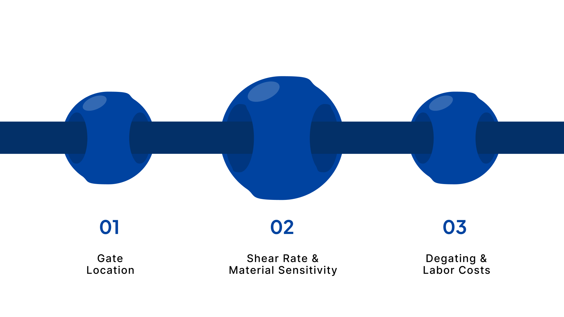
Gate Location
The gate should almost always be placed at the thickest area of the part. This allows the plastic to flow from the thick sections into the thin sections. If you gate at a thin section, the plastic may freeze before the thick area is full, leading to sink marks and structural voids.
This rule is fundamental to preventing the formation of weak spots in the polymer matrix.
Shear Rate and Material Sensitivity
Some materials are shear sensitive, meaning their molecular chains break if they are forced through a tiny opening too quickly. For materials like PVC or flame-retardant resins, larger gates, like fan or tab gates, are necessary to prevent material degradation.
The speed at which the plastic enters the mold directly impacts the physical properties of the finished product.
Degating and Labor Costs
If your project is being manufactured in a region with high labor costs, such as the United States, prioritizing automatic degating through submarine or cashew gates is essential to keep the unit price competitive.
Manual degating adds a layer of human error and variability that can be eliminated through automated gate design.
Common Defects Related to Poor Gating
If the injection molding gates are not optimized, several visual and structural defects can occur.
Defect | Likely Cause | Solution |
Jetting | Gate is too small or located in a wide-open area. | Use a tab gate or move the gate to aim at a wall. |
Gate Blush | High shear or moisture in the material. | Increase gate size or slow down injection speed. |
Splay | Moisture or overheated material at the gate. | Dry the material or reduce the injection pressure. |
Weld Lines | Improper gate location is causing flow fronts to meet. | Relocate the gate or use a diaphragm gate. |
Sink Marks | Gate froze before the part was fully packed. | Increase gate size or increase hold time. |
Conclusion
The selection of an injection molding gate is a defining moment in the product development lifecycle. It is the point where design meets reality, and where the financial feasibility of a project is often determined. Whether you prioritize the automated efficiency of a submarine gate or the flawless finish of a valve gate, the goal remains the same: to create a repeatable, high-quality component with minimal waste.
Partner with Evok Polymers for Tooling Excellence
At Evok Polymers, we believe that transparency in the engineering phase leads to success in the production phase. We don't just build molds; we develop optimized manufacturing solutions tailored to the needs of US-based engineering teams.
Why Leading Engineers Choose Evok:
Data-Driven Decisions: We use Polyestimator to provide instant feedback on how your gating choices impact your part price.
DFM-First Culture: Our team identifies potential jetting or sink issues before a single piece of steel is cut.
End-to-End Support: From material selection through tooling and final validation, we are your single point of accountability.
Ready to optimize your next injection molding project?
Request a Quote from Evok Polymers today and let our engineering team help you select the perfect gating strategy for your application.
Frequently Asked Questions (FAQs)
1. Which injection molding gate is best for cosmetic parts?
For parts where appearance is the highest priority, pin gates or valve gates are the best options because they leave the smallest vestiges. If those are too expensive, a cashew or submarine gate can hide the mark on an unexposed surface.
2. Why can't I just use the largest gate possible to ensure the mold fills?
While a large gate reduces pressure drop, it also takes much longer to cool. This increases your cycle time, which raises the cost of every part. Additionally, a large gate leaves a massive vestige that is difficult to remove without damaging the part's appearance.
3. What is the difference between a manual and an automatic gate?
Manual gates, such as edge, fan, or tab, require a human or robot to trim the part from the runner after ejection. Automatic gates, like submarine, pin, or cashew, use the motion of the mold opening or the ejection pins to shear the part away from the runner system.
4. How does gate size affect the strength of the part?
The gate size impacts how well the part is packed. If the gate is too small, the machine cannot push enough material into the cavity to compensate for shrinkage, leading to internal voids that weaken the structural integrity of the component.
5. Can a gate be moved after the mold has been built?
It is much easier to add steel than to remove it. Moving a gate usually requires welding the old gate shut and machining a new one, which is expensive and can affect the tool's life. This is why we recommend a thorough mold-flow analysis before cutting steel.