Is Your Injection Mold Tooling Actually Specced for the Job?
You've just received first samples from your new injection mold. The parts show warpage. Burn marks darken critical surfaces. Cycle times refuse to come down no matter how many process adjustments your team makes. These problems feel like process issues—temperature curves, injection speeds, hold pressures. But the real culprit was locked in months earlier, during tooling specification.
Underspecified tooling is one of the most expensive and least visible problems in injection molding. The costs accumulate silently: scrap bins fill, rework hours multiply, rejected shipments damage customer relationships, and emergency tooling modifications drain budgets.
The numbers tell the story. A documented case study found a manufacturer who chose a $12,000 overseas tool over a $49,000 domestic quote ultimately spent $49,500+ in repairs, emergency runs, and manual flash removal — a 100% cost overrun with no usable production output.
This article walks through 7 specific, observable warning signs that your tooling was underspecified — who should look for them, and what to do when you spot them.
Key Takeaways
- Sign 1: Steel was cut without a DFM review or mold flow analysis
- Sign 2: Steel grade doesn't match your resin's abrasiveness or your production volume
- Sign 3: Cooling channels are minimal or poorly positioned for your part's geometry
- Sign 4: Burn marks, short shots, or surface defects appear consistently across production runs
- Sign 5: Parts stick, drag, or distort during ejection cycle after cycle
- Sign 6: Holding tolerances requires ongoing manual process tweaks
- Sign 7: Unplanned repairs and tooling modifications have become routine costs
What "Underspecified" Injection Mold Tooling Actually Means
Tooling is underspecified when the mold design, materials, and systems were selected or scoped below what the part geometry, resin, production volume, or quality requirements actually demand. The four systems most often underspecified are:
- Cooling — insufficient channel placement or diameter for the resin's heat load
- Venting — inadequate vent depth or location for the part geometry
- Gating — gate size or type mismatched to fill requirements
- Ejection — pin count, size, or placement insufficient for part rigidity
This typically happens when upfront tooling cost becomes the primary decision driver, overriding technical requirements.
The cost logic is backwards. A tool built to a lower specification than required doesn't save money—it transfers cost downstream. Engineering decisions made during tooling specification lock in 80% of downstream costs before any steel is cut. A design change after steel is cut costs 5–10x more than optimizing the design digitally during the validation phase.
Many manufacturers end up tweaking barrel temperatures, injection speeds, and pack pressures indefinitely, trying to compensate for an underspecified mold. The 7 signs below help identify when the root cause is the tool itself, not the process. If defects persist after establishing a qualified process window, the problem is a tool design flaw—not operator error.
Warning Signs 1–3: Red Flags That Appear Before Production Even Starts
Underspecified Sign 1: No DFM Review or Mold Flow Analysis Was Part of the Tooling Engagement
Mold flow simulation and Design for Manufacturability (DFM) review are how potential tooling problems—gate location errors, weld line weaknesses, air traps, cooling imbalances—get caught and corrected before steel is cut. These aren't optional extras.
Simulation prevents expensive physical rework. Pre-steel Moldflow analysis can reduce cycle times by 11.8%, cut clamping force requirements by 45 tons, and lower material costs by 25%. Digital simulation predicts flow fronts, thermal imbalances, and trapped gas locations before any metal is machined. Modifying a mold after steel is cut costs 5-10x more than optimizing the design digitally.
The observable warning sign: If your supplier delivered a tooling quote with no DFM deliverable, no mold flow report, and no design review meeting, that's a leading indicator the specification was never validated against your part's actual requirements. The tooling was quoted, not engineered.
Underspecified Sign 2: The Steel Grade Doesn't Match Your Resin or Production Volume
Steel selection directly impacts tool lifespan and part quality. Running abrasive resins—glass-filled nylons, PBT, PPS—in soft or aluminum tooling accelerates wear on cavity surfaces, gate areas, and parting lines. The result: premature flash, dimensional drift, and surface degradation far ahead of the tool's expected lifespan.
Glass fibers act as abrasive particles under high shear. Standard pre-hardened P20 steel (28-32 HRC) will wash out gates in days when running glass-filled resins. For these applications, through-hardened H-13 or S-7 tool steel (48-58 HRC) is required.
Steel Selection by Application:
| Steel Grade | Hardness (HRC) | Expected Cycles | Best Applications |
|---|---|---|---|
| P20 | 28-32 | 100k-300k | Unfilled commodity resins (ABS, PP, PE). Will fail quickly with glass-filled materials. |
| H-13 | 48-54 | 250k-1M+ | Glass/mineral-filled engineering plastics (PA+GF, PBT+GF). Moderate to high production. |
| S-7 | 50-58 | 500k+ | Complex high-production molds needing wear and impact resistance. |
| 420 Stainless | 48-52 | High | Corrosive resins (PVC, flame retardants), high-gloss optical parts, medical applications. |
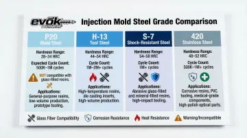
Observable signs: Flash forming at parting lines after relatively low shot counts, cavity surfaces losing finish faster than expected, or visible gate erosion all point to steel underspecified for the resin.
Underspecified Sign 3: The Cooling System Is Minimal, Generic, or Absent for the Part's Geometry
Cooling accounts for 70-80% of total injection molding cycle time, and in some applications up to 95%. A well-designed system places channels at optimal distances from cavity surfaces, accounts for hot spots in thick sections, and ensures balanced heat extraction across the part.
An underspecified cooling layout relies on minimal or straight-through channels that can't address part-specific thermal demands. Generic cooling creates hot spots that force operators to extend cycle times to prevent warpage—masking a fundamental tooling deficiency rather than solving it.
Conventional cooling design rules:
- Channels should be placed approximately 2-2.5 times the channel diameter from the cavity surface
- Waterline pitch (spacing) should be 3-5 times the cooling line diameter
- System must use turbulent flow to maximize heat transfer
- Deep cores and complex geometries require baffles, bubblers, or conformal cooling
Observable signs at this stage: A tooling design with no evidence of strategic cooling channel placement, no baffle or bubbler provisions for deep cores, or a single in/out circuit for a complex part geometry. Cycle time and warpage problems are already locked in before the first shot runs.
Conformal cooling—3D-printed channels that follow part geometry—has been shown to reduce cooling time by 75% and overall cycle time by 40% in documented case studies.
Warning Signs 4–6: Red Flags That Surface During Active Production
Underspecified Sign 4: Consistent Burn Marks, Short Shots, or Surface Defects Across Runs
Burn marks (dieseling) and short shots caused by trapped gas are almost always symptoms of inadequate venting. The mold is full of air before plastic enters. If that air isn't evacuated, it compresses under injection pressure and superheats to the point of spontaneous combustion—literally burning the polymer and chemically eroding the cavity wall.
A properly specified tool places vents at every logical gas trap location for the specific material being run. Vent depth must be precisely matched to resin viscosity:
| Material | Vent Depth (Inches) |
|---|---|
| Nylon (PA) | 0.0003 - 0.0005 |
| Acetal (POM) | 0.0005 - 0.001 |
| Polyethylene / Polypropylene | 0.0005 - 0.0012 |
| ABS | 0.001 - 0.0015 |
| Polycarbonate (PC) | 0.0015 - 0.0025 |
When burn marks, short shots, or surface defects appear consistently at the same locations every run—and don't resolve with reasonable process adjustments like reduced fill speed or temperature changes—the mold's venting specification is insufficient for the resin and geometry.
Underspecified Sign 5: Parts Consistently Stick, Drag, or Distort During Ejection
Parts that resist ejection or show drag marks indicate one of two problems: insufficient draft angle for the depth of draw and texture present, or an ejection system that wasn't sized to the part's stiffness, geometry, and material shrink behavior.
Both are tooling specification decisions, not process adjustments.
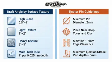
Draft angle requirements increase dramatically with texture. Textured surfaces create microscopic mechanical interlocks with the mold surface. Industry standards require:
- High Gloss (SPI A1/A2): 0.5° to 1° minimum
- Light Texture (SPI C): 1° to 2°
- Heavy Texture (SPI D / VDI 30+): 3° to 5° or more
- Mold-Tech Rule: Add 1° of draft per 0.0005"-0.0006" of texture depth
Ejector pin requirements:
- Use the largest diameter pins that fit the geometry (minimum 2mm; 4-6mm preferred)
- Place pins near deep cores, tall ribs, and tight-fitting features
- Keep pin edges at least 1.5x the wall thickness from part edges
- Ejection stroke should extend at least 5mm beyond the deepest draw
Ejection damage, distortion, or witness marks that appear at the same locations every cycle—and worsen at normal production speeds—point to inadequate draft or ejection layout. Slowing down the press isn't the fix. The tool was underspecified.
Underspecified Sign 6: Holding Tolerances Requires Constant Manual Process Adjustment
A properly specified mold, run with a validated scientific molding process, should produce in-tolerance parts within a defined and repeatable process window.
If operators must constantly adjust barrel temperatures, pack pressure, or hold time to keep dimensions in spec, the mold's cavity precision, steel-safe design execution, or shrinkage compensation was likely not specified correctly at the tooling stage.
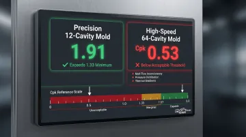
Process capability metrics reveal tooling deficiencies. Process Capability Index (Cpk) measures a process's ability to produce parts within specified tolerances. A Cpk of 1.33 is the standard minimum for acceptance; automotive and critical safety applications require Cpk ≥1.67. No amount of process optimization compensates for a tool that was underspecified from the start.
Observable warning signs:
- High measurement variability from cavity to cavity in multi-cavity tools
- Need to re-qualify the process frequently after material lot changes
- Inability to achieve Cpk >1.33 despite extensive process optimization
- Parts drift out of spec as the tool heats up or cools down
In a comparative study, a precision 12-cavity mold achieved Cpk of 1.91, while a large 64-cavity high-speed mold yielded a failing Cpk of 0.53. The 64-cavity tool failed due to inconsistencies in melt flow, pressure distribution, and thermal gradients. The gap came down to tooling specification and execution quality—not process.
Warning Sign 7: Tooling Modifications and Unplanned Repairs Are Becoming Routine
Every unplanned tooling modification — added vents, enlarged gates, extra ejector pins, welded cavity surfaces, dimensional corrections — represents a cost that a properly specified tool should never generate. When these become routine rather than rare, the cumulative spend typically exceeds the price gap between what was originally quoted and what the job actually required.
Distinguish routine maintenance from structural rework:
- Routine maintenance: Cleaning vents, replacing ejector pins, re-polishing surfaces at high shot counts
- Structural rework: Gate changes, cooling additions, vent additions, cavity dimensional corrections
According to Plastics Today, high-volume Class 101 molds typically require 30–40% of their original cost in routine maintenance over their lifespan. Structural rework is a different category entirely — it signals design obsolescence or premature failure, not normal wear.
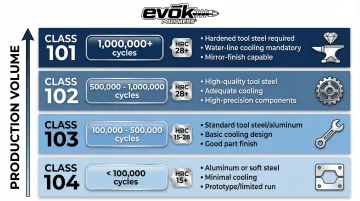
SPI Mold Classifications and Expected Lifespan:
| SPI Class | Expected Cycles | Minimum Requirements |
|---|---|---|
| Class 101 | 1,000,000+ | Extremely high volume. Cavities/cores hardened to minimum 48 HRC. Guided ejection and parting line locks required. |
| Class 102 | Up to 1,000,000 | Medium to high volume. Cavities/cores hardened to minimum 48 HRC. |
| Class 103 | Up to 500,000 | Medium volume. Cavities/cores must be 28 HRC or higher. |
| Class 104 | Up to 100,000 | Low volume. Non-abrasive materials. |
Business-level signal: The previous six signs surface on the shop floor — engineers and quality teams catch them first. This one shows up in the finance and operations review. If breakdown frequency is climbing before the tool hits its expected cycle count, compare your actual production volume against the SPI class your mold was built to. That gap is the diagnosis. A formal mold audit against your SPI classification requirements will confirm whether the tool needs replacement or whether a design correction can extend its usable life.
What to Do When You Recognize These Warning Signs
Start with a Tooling Audit
A structured review of the existing tool's design drawings, steel certification, cooling layout, venting, gating, and ejection system against the part's current requirements will identify which specification gaps are driving the problems. This is especially critical before committing budget to another round of tooling.
A qualified tooling and design partner should bring:
- Upfront DFM analysis and mold flow simulation
- Pre-molding design review with transparent documentation
- Clear explanation of every specification decision and its cost implications
- Steel grade selection matched to resin type and annual volume
- Cooling channel layout reviewed against part wall thickness and geometry
- Venting locations called out explicitly in the tool design
At Evok Polymers, pre-tooling design reviews are a standard part of every engagement — not an optional add-on. Our team is direct about cost-versus-specification tradeoffs so customers can make informed decisions before tool fabrication begins.
Use these questions to pressure-test any new tooling quote:
- What steel grade is specified and why is it appropriate for this resin and volume?
- Is a DFM review and mold flow analysis included in the scope?
- How are cooling channels designed for this specific part geometry?
- Where are vents located and how were vent depths determined?
- What is the basis for gate size, type, and location?
- What draft angles are specified and how do they account for texture?
- How many ejector pins are specified and where are they placed?
Frequently Asked Questions
Frequently Asked Questions
What exactly does "underspecified" injection mold tooling mean?
Underspecified tooling means the mold's design, materials, or systems (cooling, venting, gating, ejection) were scoped below what the part geometry, resin type, and production volume actually require. Pressure to cut upfront cost drives most of these decisions—and the result is higher downstream costs through scrap, rework, extended cycles, and premature tool failure.
Can underspecified injection mold tooling be fixed, or does it need to be fully replaced?
It depends on severity. Some deficiencies—adding vents, modifying gates, adding ejector pins—targeted modifications can fix. Others—wrong steel grade for abrasive resins, inadequate cooling layout—require a full retool. A tooling audit determines which approach makes financial sense.
How does cooling system design affect injection molding cycle time and part quality?
Cooling typically accounts for 70–80% of total cycle time—and up to 95% in complex geometries. A poorly designed cooling system creates hot spots that cause warpage, sink marks, and extended cycle times that cannot be fully compensated for through process adjustments. Proper cooling channel placement—approximately 2–2.5x channel diameter from the cavity surface—is critical for both speed and quality.
What is a mold flow analysis and why does it matter for tooling specification?
Mold flow analysis is a simulation that predicts how molten plastic will fill, pack, and cool inside a mold design before any steel is cut. It allows engineers to optimize gate location, venting, cooling, and wall thickness to avoid defects that would otherwise only appear after tooling is built—when fixes cost 5–10x more.
What steel grade should injection mold tooling be made from?
Steel selection depends on resin type, volume, and geometry. Glass-filled resins demand hardened steels like H-13 or S-7; commodity resins in lower volumes can use P20; corrosive resins like PVC require 420 Stainless. Mismatching steel to application is a primary driver of premature tool wear.
What questions should I ask before approving an injection mold tooling quote?
Start with three: What steel grade is specified and why? Is a mold flow analysis included? How are cooling channels designed for this part geometry? If a supplier can't answer these clearly, they're quoting to a price point—not to your requirements.