Introduction
Engineers and product developers still approach injection molding with assumptions shaped by past projects, vendor pitches, or outdated information — and those assumptions cost them time and money. A misplaced belief about tooling costs can blow your budget by 40%. Skipping design-for-manufacturability review can multiply your fix-it costs by 100x once steel is cut. Dismissing injection molding for "low volume" can leave you paying 3x more per part than necessary.
Every one of those scenarios comes from real projects. Paul Dathe and the EVOK team have spent 25+ years correcting these exact misconceptions across medical devices, powersports, semiconductor equipment, and consumer packaging. What follows is what the data actually shows — not what the myths claim.
TLDR: 7 Myths at a Glance
- Myth #1: The upfront tooling cost is your biggest injection molding expense
- Myth #2: Any CAD design can go straight to tooling
- Myth #3: Mold lifespan is binary — tools either last forever or fail early
- Myth #4: Low-volume runs can't justify injection molding costs
- Myth #5: Plastic parts can't match metal in precision or structural performance
- Myth #6: You can always tweak process parameters to fix part defects
- Myth #7: The process generates excessive waste with no practical recovery path
Myth #1: The Upfront Tooling Cost Is Your Biggest Injection Molding Expense
The Myth: Engineers and procurement teams fixate on the mold's purchase price as the primary cost driver and try to minimize it above all else.
The Reality: Mold cost typically represents only a fraction of total program spend when you factor in part price × lifetime volume + maintenance. Research by Fagade & Kazmer demonstrates that material cost constitutes 50% to 80% of total part cost, while processing cost (driven by machine hourly rates and cycle time) accounts for 40% to 80%. Tooling costs are amortized over production quantity, meaning their per-unit impact diminishes significantly at scale.
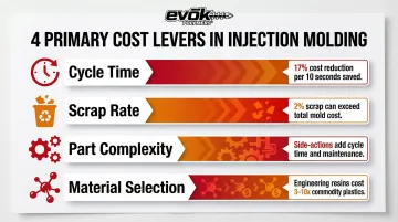
The Real Cost Levers
The factors that drive unit economics dwarf the initial tool quote:
- Cycle time: Shaving 10 seconds off a 60-second cycle reduces cost per part by 17% over a million-unit run
- Scrap rate: A 2% scrap rate on a high-volume program can cost more than the entire mold
- Part complexity: Features requiring side-actions or lifters add cycle time and maintenance burden
- Material selection: Engineering resins can cost 3-10x more than commodity plastics
Those per-unit costs compound fast. Cutting corners on tool quality to save $5,000 upfront often drives up per-part cost downstream — and maintenance adds up: high-volume molds with complex mechanisms require 30% to 40% of their inflation-adjusted value in maintenance over the tool's life, while simpler low-volume molds need only 5% to 10%.
The "Cheapest Quote Wins" Trap
A lower-priced tool from an unvetted supplier brings hidden costs:
- Troubleshooting trips: Flying engineers to a distant moldmaker for on-site fixes
- Post-delivery delays: Waiting weeks for tweaks that should have been caught in design review
- Uncertain maintenance ownership: No clear protocol when the tool needs service at 200,000 cycles
Any one of these can derail a program launch — and combined, they routinely exceed the savings from the cheaper tool.
EVOK addresses this by mapping cost implications before tooling begins. Decisions made in the design phase — wall thickness uniformity, gate placement, cooling channel layout — directly affect what you pay per part over a million-unit run. Quantifying those tradeoffs early means engineers aren't discovering avoidable cost drivers after the mold is already cut.
Myth #2: Any CAD Design Can Go Straight to Tooling
The Myth: Many engineers assume that if a part can be modeled in CAD and looks right on screen, it's ready to be cut into steel.
The Reality: Design for Manufacturability (DFM) is the difference between a successful first shot and expensive mold rework. Missing critical DFM fundamentals causes defects or requires modifications that can cost significantly more after tooling.
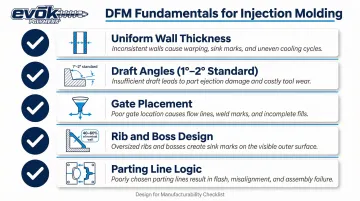
DFM Fundamentals for Injection Molding
Key design elements that must be addressed before tooling:
- Uniform wall thickness: Variations cause differential cooling, leading to warpage and sink marks
- Draft angles: Minimum 0.5° on vertical faces; 1° to 2° is standard, with 3° minimum for shutoffs or light texture
- Gate placement: Determines flow pattern, weld line location, and ease of post-processing
- Rib and boss design: Thickness should be 40% to 60% of adjacent nominal wall to avoid sink marks
- Parting line logic: Must allow proper mold opening without damaging the part
Geometry Traps and Undercuts
Some geometries physically prevent proper ejection or create inconsistent fill and cooling:
- Undercuts: Features that prevent straight ejection require side-actions or lifters, adding cost and cycle time
- Thin unsupported ribs: Can flex during ejection or break under load
- Sharp internal corners: Create stress concentrations and flow hesitation
- C-shapes and open geometries: Can be structurally weak if not reinforced correctly
The Cost of Skipping Design Review
Barry Boehm's cost-of-change curve demonstrates that fixing a problem after delivery is upwards of 100 times more expensive than fixing it during early design phases. A $500 CAD revision becomes a $50,000 tooling modification once steel is cut.
Standard Wall Thickness Guidelines:
| Material | Recommended Wall Thickness |
|---|---|
| ABS | 0.045 in. to 0.140 in. |
| Polycarbonate | 0.040 in. to 0.150 in. |
Source: Protolabs Design Guidelines
Mold Flow Analysis: Predicting Problems Before Steel Is Cut
Mold flow simulations predict fill patterns, weld lines, warpage, and cooling behavior before a single piece of steel is cut. In a case study by Machino Plastics, Autodesk Moldflow simulation identified that adding a 1.25mm flow leader resolved short shots, eliminating the need for an additional gate that would have increased tooling costs and created knit lines — a 1-2% material addition that saved thousands in tooling modifications.
EVOK's pre-molding design reviews — led by Sr. Industrial Designer Shawn Monitor — have reduced tooling risk on large-scale projects. Shawn specializes in building complex mechanical and visual prototypes across multiple materials, confirming part solutions before committing to tooling. That front-loaded review is how EVOK consistently catches problems at the $500 stage instead of the $50,000 one.
Myth #3: Injection Molds Either Last Forever or Wear Out Too Quickly
Some engineers expect a mold to run unlimited cycles with zero maintenance. Others write off longevity entirely, treating wear as unpredictable. Both positions miss the mark.
Mold lifespan is highly predictable when steel selection and maintenance discipline are aligned from the start. The industry standard SPI AR-101 classifications make that clear.
Realistic Lifespan Data by Tool Class
| SPI Class | Expected Cycles | Typical Material | Key Requirements |
|---|---|---|---|
| Class 101 | 1,000,000+ | Hardened Steel (H13) | Cavity/cores hardened to 48 RC min |
| Class 102 | Up to 1,000,000 | Hardened Steel | Cavity/cores hardened to 48 RC min |
| Class 103 | Up to 500,000 | Pre-hardened Steel (P20, NAK80) | Cavity/cores 28 RC min |
| Class 104 | Up to 100,000 | Mild Steel or Aluminum | Low production; non-abrasive materials |
| Class 105 | Up to 500 | Aluminum, Cast Metal, Epoxy | Prototype only |
Source: SPI AR-101 Mold Classifications
Specific steel grades deliver predictable performance: P20 steel typically yields 200,000 to 300,000 shots, NAK80 yields 400,000 to 500,000 shots, and H13 can endure up to 1,000,000 shots. Aluminum molds generally last 2,000 to 10,000 parts.
Those cycle targets assume the mold is treated well. Three failure patterns cut life short well before the theoretical maximum.
The Three Killers of Mold Life
- Disuse damage — Molds left in humid storage without preservation develop rust on precision surfaces, requiring expensive refinishing before they can run again.
- Abrasive misuse — Running glass-filled or mineral-reinforced resins without adjusted maintenance schedules accelerates cavity wear faster than the steel grade was rated for.
- Deferred maintenance — Skipping ejector pin inspections, vent cleaning, or cooling channel descaling turns minor degradation into costly unplanned downtime.

Preventing all three comes down to one discipline: cycle-based scheduling. Calendar dates are unreliable — a mold that runs 50,000 cycles in six months needs attention far sooner than one that hits the same count in two years.
What a Basic Maintenance Protocol Should Include
- Cooling channel inspection: Verify flow rates and descale to prevent invisible degradation
- Ejector pin inspection: Check for binding and wear that causes sticking
- Vent depth measurement: Typically 0.0005 to 0.002 inches to prevent gas traps
- Parting line cleaning: Remove flash and buildup that affects seal
- Core/cavity inspection: Check for erosion, especially with abrasive resins
Factor Maintenance into Program Planning
Engineers should budget maintenance costs (typically a percentage of original tool cost) from day one. As noted earlier, complex high-volume molds require 30% to 40% of their inflation-adjusted value in maintenance over their life, while simpler tools need only 5% to 10%. Planning for this upfront prevents surprise expenses and production interruptions.
Myth #4: Injection Molding Only Makes Financial Sense at High Production Volumes
The Myth: Because mold costs are real and significant, engineers assume the process is cost-prohibitive unless they're making hundreds of thousands of parts.
The Reality: Injection molding becomes more cost-effective than 3D printing at volumes as low as 130 units, depending on part complexity and material. Aluminum prototype tools, bridge tooling, and family molds bring per-unit economics into range for lower volumes.
Break-Even Economics: When Injection Molding Wins
| Quantity | 3D Printing (SLS) | Urethane Casting | Injection Molding |
|---|---|---|---|
| 10 | $33.21 | $57.20 | $945.53 |
| 50 | $30.35 | $41.40 | $189.87 |
| 100 | N/A | $30.16 | $96.14 |
| 500 | N/A | $25.40 | $20.43 |
| 1,000 | N/A | N/A | $10.92 |
Source: Fictiv Manufacturing Cost Analysis
The data shows that urethane casting maxes out around 300 parts due to tooling degradation, while injection molding unit costs drop exponentially. Low-volume injection molds machined from aluminum or P20 steel are typically ready for parts production in about two weeks.
That two-week lead time matters because tooling strategy directly controls where your break-even point lands.
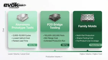
Tooling Strategy Options for Lower Volumes
- Aluminum prototype tools handle 2,000–10,000 cycles with lower upfront cost and faster lead times
- Pre-hardened steel (P20) bridge tooling extends production capacity to 100,000–300,000 parts
- Family molds combine multiple part cavities in one tool, spreading tooling cost across your product line
Where the Myth Causes Real Harm
The real cost of this myth is overpaying — $30–40 per part when a modest tooling investment would drop that to $10–15. Companies stay on 3D printing or urethane casting well past the point where injection molding becomes the smarter call, compounding the gap with inconsistent material properties and longer lead times.
The Lesson: Before dismissing injection molding on cost, run a break-even analysis that accounts for total program volume, part complexity, material requirements, and timeline. For many programs, the tooling investment pays back within the first 200–500 parts.
Myth #5: Plastic Parts Can't Match Metal in Precision or Structural Performance
The Myth: Engineers trained in metals often apply a blanket assumption that plastic parts are dimensionally imprecise, weak, or unreliable for load-bearing applications.
The Reality: Engineering-grade resins deliver tensile strength, stiffness, and thermal performance that directly substitute for metal in many structural applications. The catch: direct design translation from metal fails because plastics behave differently under thermal and moisture conditions.
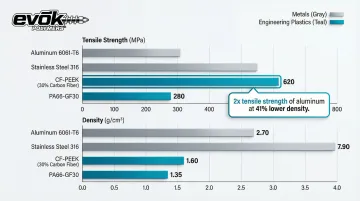
Material Science: High-Performance Plastics vs. Metals
| Material | Density (g/cm³) | Tensile Strength (MPa) | Tensile Modulus (GPa) |
|---|---|---|---|
| Aluminum 6061-T6 | 2.70 | ~320 | 68.9 |
| Stainless Steel 316 | 8.00 | 550 | 193.0 |
| CF-PEEK (30% Carbon Fiber) | 1.59 | Up to 689 | 19.7 |
| PA66-GF30 (30% Glass Fiber) | 1.36 | 130-190 | 7.2-10.0 |
Sources: PEEK vs. Aluminum comparison, BASF Ultramid datasheet, ASM Material Data
Carbon-fiber reinforced PEEK delivers more than double the tensile strength of Aluminum 6061-T6 at a 41% reduction in density. PA66-GF30 delivers 130–190 MPa tensile strength at roughly half the weight of aluminum — and both materials outperform metals in corrosion and chemical resistance for environments where stainless steel would corrode or degrade.
The Tolerance Reality: Not a Process Limitation, a Design Error
Injection molded parts absolutely can hold tight tolerances — but the tolerance must be specified appropriately for plastic behavior. Standard commercial tolerances for manufactured parts are ±0.250 mm (0.010"), while the resin tolerance for finished molded parts is typically ±0.002 in./in. (0.051mm/mm).
The key differences:
- Material shrink rates: Plastics shrink 0.3% to 2% during cooling; this must be designed into the mold
- Thermal expansion: Plastics expand and contract at rates 3 to 10 times greater than metals
- Moisture absorption: Unfilled nylon 6/6 can absorb 5% to 8% moisture by weight when immersed, resulting in a 2% increase in length
Applying machined-metal tolerances (±0.001" across the board) to plastic parts is a design error, not a process limitation. The fix is straightforward: specify tolerances that account for material behavior, and specify glass-filled or mineral-filled resins when dimensional stability is non-negotiable.
Myth #6: You Can Always Tweak Process Parameters to Fix Part Defects
Process engineers sometimes believe that sink marks, warpage, short shots, or dimensional drift can be dialed out by adjusting injection speed, pressure, temperature, or cooling time. In practice, process parameters have a defined operating window. Chasing defects through parameter adjustments — without addressing the actual root cause — leads to instability and entirely new defects.
What Parameters Can and Cannot Fix
Process parameters CAN compensate for:
- Minor variation within a stable process
- Small changes in ambient temperature or humidity
- Slight material lot-to-lot variation
- Optimizing cycle time within a proven process window
Process parameters CANNOT fix:
- Fundamentally flawed gate locations
- Poorly designed cooling channels
- Non-uniform wall thickness
- Inadequate venting
- Wrong material selection
The Danger of Extreme Parameters
Cranking up injection pressure to mask short shots creates new problems:
- Flash: Excessive injection pressure forces molten material into mold gaps, blowing the clamp open
- Burn marks: High injection speeds or excessive melt temperatures cause material degradation
- Tool damage: Running outside recommended parameters accelerates mold wear
The consequences can be irreversible. In one documented case, excessive shear rates at the gate caused lower molecular weight additives in a flame-retardant polyamide to degrade, resulting in severe color variation. The fix required a tooling change — increasing gate depth by 0.005 inches — not a process change.
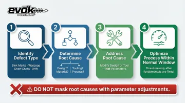
Root Cause Logic
When parameters are doing the work that design or tooling should be doing, the process becomes fragile. A mold that requires extreme settings just to produce acceptable parts is a liability waiting to surface. The correct approach:
- Identify the defect type: Sink marks, warpage, short shots, dimensional drift
- Determine root cause: Is it design, tooling, material, or process?
- Address the root cause: Modify design or tool if needed; don't mask with parameters
- Optimize process within normal window: Fine-tune after fundamentals are correct
Getting the process dialed in matters — but only after design, tooling, and material are right. Parameter optimization applied to a flawed foundation produces inconsistent parts and unpredictable scrap rates across production runs.
Myth #7: Injection Molding Generates Excessive, Unrecoverable Waste
The Myth: Skeptics and cost-conscious buyers often assume that runners, sprues, and scrap from injection molding represent significant material waste that harms both cost and sustainability goals.
The Reality: Injection molding is highly material-efficient compared to subtractive manufacturing. Thermoplastic runners and sprues are routinely reground and recycled back into production — and hot runner systems eliminate solidified waste entirely.
Material Utilization in Practice
- Most injection molding screw designs accommodate regrind without issue; processing problems typically only develop when regrind content reaches 20–25%
- Hot runner systems keep plastic molten within the runners, completely eliminating solidified runner waste and reducing cycle times
- CNC machining cuts away material from a solid billet; injection molding — optimized with hot runners and regrind — approaches near-100% material utilization
Sustainable Material Options
For programs with environmental targets, circular material options have expanded significantly:
- Post-consumer recycled (PCR) resins: SABIC's LNP Elcrin copolymer resins contain up to 75% PCR content; their NORYL PCR-based technology uses 30% PCR content and cuts global warming potential by 10%
- Bio-based resins derived from plant sources reduce fossil fuel dependence without requiring process overhauls
- BASF's ecovio is a certified compostable biopolymer validated for multi-cavity thin-wall injection molding
When hot runners and regrind protocols are dialed in, material loss in injection molding is a fraction of what most engineers expect — often under 5% in optimized programs. Choosing the right resin strategy from the start determines how far you can push those numbers.
Frequently Asked Questions
What is the life expectancy of an injection mold?
Mold life varies widely based on steel grade, resin type, and maintenance. Aluminum prototype tools last roughly 10,000 cycles, while hardened production steel (H13) can exceed 1,000,000 cycles. Proper maintenance protocols are the single biggest factor in achieving maximum tool life.
Is injection molding cost-effective for low-volume production runs?
Low-volume runs can be viable with bridge tooling or aluminum molds. The decision comes down to a part-specific break-even analysis: weigh tooling investment against per-part savings versus alternatives like 3D printing or urethane casting. Injection molding typically becomes cost-competitive above 130–500 units, depending on part complexity.
How long does it typically take to build an injection mold?
Simple aluminum tools can be completed in 2–4 weeks, while complex hardened steel production molds may take 8–16 weeks or more, depending on part geometry, number of cavities, and any required side-actions or lifters.
Can you change a part design after the mold has already been built?
Minor modifications (adding steel to reduce a dimension, adjusting a gate) are often feasible. Removing steel to increase a dimension is a different story — that typically requires a new insert or mold entirely. Front-end DFM review exists precisely to catch these issues before the tool is cut.
What tolerances can injection molding realistically hold?
Commercial tolerances for injection molded parts are typically ±0.005″ to ±0.010″ for many resins. Tighter precision tolerances are achievable but must account for material-specific shrinkage, thermal behavior, and cavity-to-cavity variation rather than simply borrowing machined-metal tolerance callouts.
Are engineering plastics strong enough to replace metal components?
Engineering-grade resins like PEEK, glass-filled nylon, and polycarbonate can match or exceed metal in specific performance metrics (weight-to-strength, corrosion resistance, chemical resistance). Successful metal-to-plastic conversions depend on rigorous material selection — someone with deep resin knowledge needs to drive that process, not just compare datasheets.