Introduction
A single overlooked design decision in injection molding can cascade into six-figure losses by the time production begins. When a General Motors team ignored Moldflow warpage predictions during the design phase, the oversight cost $101,305 and 43 days in rework to correct clip interference and wall thickness issues after steel was cut.
The flip side: proactively using simulation to relocate a gate and eliminate a weak weld line saved GM an estimated $1.1 million in unexpected punch costs and resin price adjustments.
Both outcomes trace back to timing. Defects, rework, and scrapped tooling don't just hurt quality — they destroy schedules and budgets. Most of these failures share one thing: they're caught too late.
This article covers 10 mistakes spanning design, material selection, tooling, process setup, and partner choice—and what engineers and OEM buyers can do to avoid each one.
Key Takeaways
- Inconsistent wall thickness and missing draft angles cause most tooling rework — fix these at the design stage
- Wrong material choice or improper drying introduces defects that process tuning cannot fix
- Underinvesting in tooling and poor cooling design create chronic defects and longer cycle times
- Skipping validation and deferring mold maintenance reduce yield and shorten tool life
- The costliest mistake: treating injection molding as a commodity purchase instead of a design-and-manufacturing partnership
Design-Stage Mistakes That Cost You Later
The design phase is where injection molding costs are locked in—not on the shop floor. Mistakes made in CAD are exponentially cheaper to fix than mistakes discovered after steel is cut. A design flaw caught during a DFM review might cost a few hours of engineering time; the same flaw discovered during first article inspection can require thousands of dollars in tool modifications or complete retooling.
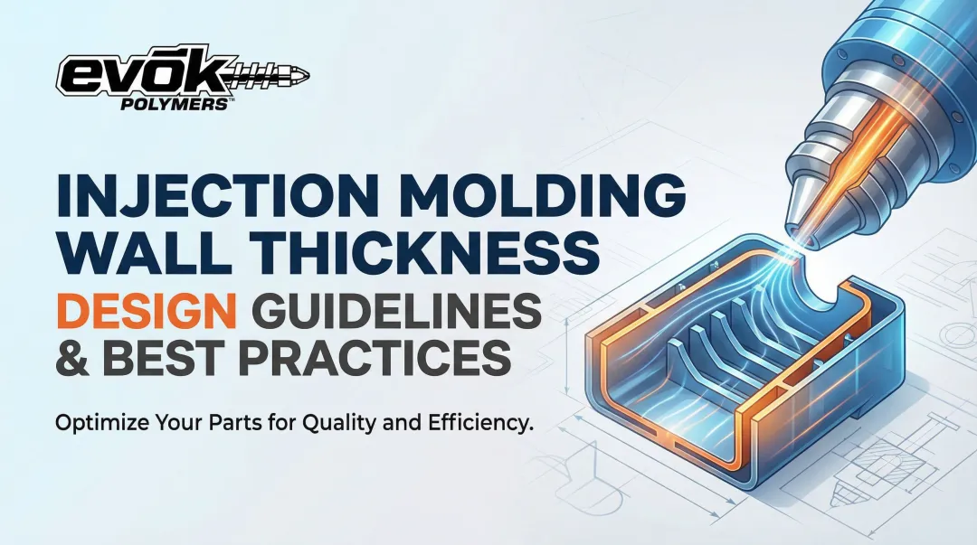
Mistake 1: Inconsistent Wall Thickness
Non-uniform wall thickness causes the melt to flow and cool at different rates, creating sink marks, warping, and internal stress. It's one of the most common root causes of post-production rework.
Wall thickness tolerances vary by material type:
- Amorphous polymers (ABS, polycarbonate): maintain wall sections within ±25% of nominal thickness
- Semi-crystalline polymers (nylon, polypropylene): keep within ±15% due to higher shrinkage rates
- General standard: wall thickness should stay within 40–60% of adjacent walls
When thick sections cool slower than thin sections, the core solidifies last and pulls the outer skin inward—producing visible sink marks and internal voids. Where thick sections are structurally necessary, use coring or ribbing to maintain uniform wall thickness throughout the part.
Correcting wall thickness after a tool is built follows the "steel safe" principle: removing metal to thicken a wall is relatively straightforward, but adding metal to thin a wall requires remaking the mold insert or complete retooling—a prohibitively expensive fix.
Each design mistake compounds the next. Draft angles are just as foundational as wall thickness—and just as easy to overlook.
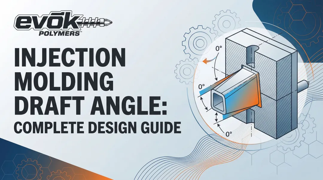
Mistake 2: Ignoring Draft Angles
Draft angles prevent parts from dragging, scratching, or sticking during ejection. Vertical walls make ejection difficult and lead to drag marks, part damage, or stuck parts that slow cycle times and damage the tool.
Standard draft angle recommendations:
- Minimum for near-vertical requirements: 0.5°
- Standard for smooth surfaces: 1° to 2°
- General rule of thumb: 1° of draft per 1 inch of cavity depth
Textured surfaces require significantly more draft to clear micro-undercuts. Add 1.5° of draft for every 0.001 inch of texture depth. Light textures require a minimum of 3°, while medium to heavy textures require 5° or more.
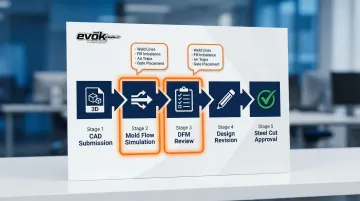
Mistake 3: Skipping Mold Flow Analysis and DFM Review
Mold flow simulation predicts how plastic will fill the cavity before a single dollar is spent on steel. Teams that skip it routinely discover avoidable defects only after tooling is cut—at a fraction of the cost to fix earlier.
Computer-Aided Engineering (CAE) analysis reveals problems that aren't visible in CAD alone:
- Short shots and fill imbalances from poor gate placement
- Weld line locations that fall on high-stress geometry
- Air traps caused by inadequate venting
- Flow hesitation and premature freeze-off in thin sections
A formal Design for Manufacturability (DFM) review with an experienced injection molding partner uncovers gate placement issues, material incompatibilities, and structural weaknesses that would otherwise result in tooling revisions or launch delays. At EVOK, the team runs pre-molding design reviews on every project to catch these risks before steel is cut—keeping customers out of costly modification cycles.
Material Selection and Handling Errors
Material decisions are binding. Once a resin is specified and tooling is cut to its shrink rate, switching materials often means retooling. Improper handling of the chosen material introduces defects that are nearly impossible to eliminate through process adjustments alone.
Mistake 4: Choosing the Wrong Resin for the Application
Selecting a material based on cost alone without evaluating the end-use environment leads to field failures, warranty claims, or the need to requalify the part in a new material—often requiring tooling modifications to accommodate a different shrink rate.
Critical evaluation factors:
- Temperature exposure range
- Chemical contact and resistance
- UV stability requirements
- Impact and structural load requirements
Environmental Stress Cracking (ESC) accounts for approximately 25% of plastic component failures. Documented failures include ABS mirror housings cracking due to phthalate plasticizer migration from PVC-coated steel clamps, and polycarbonate headlight lenses fracturing after exposure to isopropanol-based cleaning fluids.
Switching resins after a mold is built introduces dimensional risks that can invalidate the entire tool. Substituting amorphous polycarbonate (0.6%–0.8% shrinkage) with semi-crystalline PA66 (0.7%–3.0% shrinkage) produces parts that are undersized and prone to warpage. Complete cavity resizing is typically required.
Mistake 5: Improper Material Handling and Drying
Hygroscopic resins like nylon, polycarbonate, and ABS absorb moisture from the air. Molding wet material causes splay marks, silver streaking, voids, and reduced mechanical properties. Even a correctly specified resin produces defective parts without proper drying to manufacturer-specified moisture content before processing.
The deeper risk is hydrolytic degradation: moisture breaks down polymer chains, reduces molecular weight, and compromises mechanical strength even when no cosmetic defects are visible.
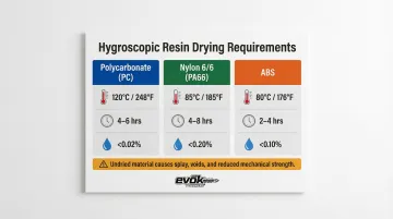
Drying requirements for common hygroscopic resins:
| Resin Type | Drying Temp | Drying Time | Max Moisture Content |
|---|---|---|---|
| Polycarbonate (PC) | 120°C | 2-4 hours | < 0.02% |
| Nylon 6/6 (PA66) | 80°C | 2-4 hours | < 0.20% |
| ABS | 80°C-95°C | 2-4 hours | < 0.10% |
Desiccant dryers must maintain strict dew points to hit these thresholds. Drying protocol alone isn't enough — contamination during handling creates its own defect stream:
- Mixing regrind at incorrect ratios
- Using uncleaned hoppers during material changeovers
- Inconsistent colorant dosing
Each of these variables introduces part-to-part inconsistency that process tuning cannot fully correct.
Tooling and Process Parameter Mistakes
Tooling represents the largest upfront capital investment in injection molding. Process parameters, on the other hand, are your daily operational levers. Get either wrong, and you pay — tooling mistakes hit hard once, while process errors compound quietly across every production run.
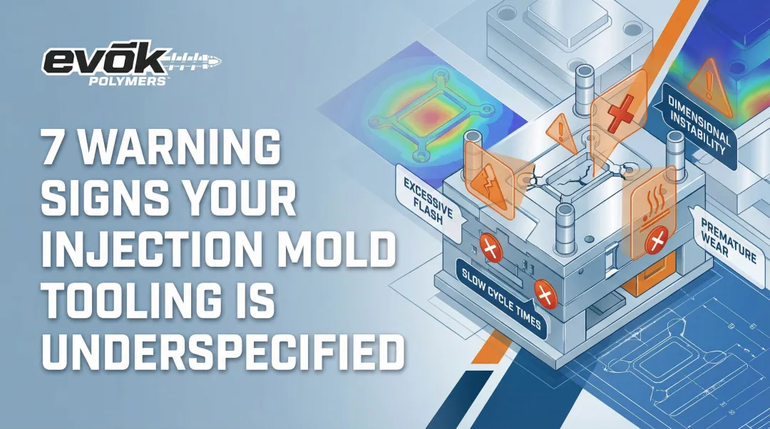
Mistake 6: Underinvesting in Tooling
Choosing the lowest-bid tool creates a false economy. Soft-steel or poorly engineered tools wear faster, hold looser tolerances, and require more frequent maintenance and repair.
Tool steel selection dictates lifespan:
| Steel Grade | Hardness (HRC) | Expected Shot Life | Ideal Application |
|---|---|---|---|
| P20 (Pre-hardened) | 28-32 HRC | 200,000-500,000 shots | Medium volume, non-abrasive materials |
| H13 (Hardened) | 48-52 HRC | 800,000-1,000,000+ shots | High volume, glass-filled resins |
| 420SS / S136 | 46-52 HRC | 1,000,000+ shots | Corrosive resins, optical clarity, medical |
A worn tool produces flash, dimensional drift, and surface defects that cannot be corrected through process adjustments—the tool itself must be repaired or replaced. As parting lines deteriorate, flash becomes inevitable.
Mistake 7: Poor Gate Placement and Runner Design
Gate location controls where and how plastic enters the cavity—affecting fill balance, weld line placement, surface appearance, and the ability to pack out the part.
Common gate placement errors:
- Gating into a cosmetic surface
- Under-gating a large part
- Locating the gate where weld lines fall in high-stress areas
Suboptimal gate placement forces weld lines into structural areas, reducing local strength by up to 80%. Gating into thin areas causes premature freeze-off, preventing packing pressure from reaching thicker sections and causing sink marks.
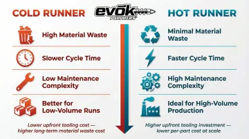
Runner system comparison:
| System Type | Material Waste | Cycle Time | Maintenance |
|---|---|---|---|
| Cold Runner | High (solidified sprue/runner scrap) | Slower (waiting for runner to cool) | Low complexity |
| Hot Runner | Minimal (material stays molten) | Faster (no runner cooling) | High complexity |
Cold runners work well for low-volume runs where tooling simplicity matters. For high-volume production, hot runners eliminate regrind waste and cut cycle times — the higher upfront complexity pays for itself quickly at scale.
Mistake 8: Neglecting Cooling System Design
Cooling time accounts for 50% to 80% of the total injection molding cycle. Poorly designed cooling channels lead to uneven cooling, warping, extended cycle times, and higher per-part costs.
Traditional straight-drilled cooling channels cannot follow complex part geometries, creating hot spots and differential shrinkage. Conformal cooling channels that follow the exact contour of the mold cavity reduce cooling time by 30% on average — and up to 70% in highly complex geometries.
That time savings also improves part quality: conformal cooling reduces maximum part warpage by approximately 25% by eliminating temperature gradients. Additive-manufactured conformal cooling inserts are valuable for high-volume or complex parts where cycle time reduction directly impacts profitability.
Quality, Validation, and Maintenance Oversights
Even a well-designed part in the right material with a good tool can fail in production if validation is skipped and maintenance is deferred. These mistakes manifest slowly—as creeping scrap rates, dimensional drift, or tool failures at the worst possible moment.
Mistake 9: Skipping Process Validation
Process validation establishes and documents a robust, repeatable process window. This separates a tool that works in a first article from one that consistently produces good parts at volume.
Without a validated process, scrap rates vary by shift, operator, or machine—and defects reach the customer. For regulated industries like medical devices and aerospace, validation is a compliance requirement under FDA 21 CFR 820.75, ISO 13485, and AS9100.
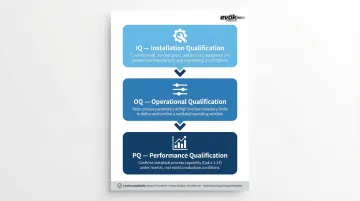
Validation protocol:
- Installation Qualification (IQ): Confirms the mold, press, and auxiliary equipment are installed correctly
- Operational Qualification (OQ): Tests process parameters at high and low limits to define a robust operating window
- Performance Qualification (PQ): Runs the process under normal production conditions to confirm statistical capability (Cpk)
In 2024, the FDA issued a warning letter to Philips for failing to validate the injection molding process of a CT scanner data cable. This nonconformance led to 64 field complaints of cable connection failures, signal loss, and a costly field correction.
Mistake 10: Neglecting Mold Maintenance
Deferred mold maintenance compounds costs over time. Common failure modes include:
- Clogged vents — trapped air superheats, causing dieseling that burns parts and erodes tool steel
- Worn or broken ejector pins — result in stuck parts, unplanned downtime, and damaged cavities
- Deteriorated parting line surfaces — allow flash to form, increasing secondary finishing costs
A planned preventive maintenance schedule protects tool life and production consistency. In one case study, inadequate venting resulted in a 44% reject rate; switching to active vacuum venting brought the reject rate to zero.
Production tools are built for specific shot lifecycles, but neglected maintenance cuts that life dramatically. A hardened H13 tool rated for 1,000,000+ shots may fail at 400,000 without scheduled maintenance intervals.
The Costliest Mistake of All: Treating Injection Molding as a Commodity
Many buyers select injection molding partners on price alone, without evaluating engineering depth, DFM capability, or transparency in cost structure. This leads to surprise tooling revisions, quality escapes, and missed launch dates that dwarf any initial savings.
A true manufacturing partnership looks nothing like a transactional quote-and-ship relationship. It includes proactive DFM reviews before tooling is cut, mold flow analysis, upfront and itemized cost structures, and a shared stake in the outcome.
What partnership looks like in practice:
- Surfaces gate placement issues, wall thickness problems, and material risks before steel is cut
- Provides itemized cost breakdowns covering tooling, cycle time, and material components
- Selects materials based on end-use environment, not lowest unit price
- Validates processes to ensure consistent quality at volume
- Schedules mold maintenance to protect tool life and production consistency
With 25 years of injection molding expertise and a Six Sigma black belt approach, EVOK serves OEMs as a design-and-manufacturing partner, not a parts vendor. Pre-molding design reviews catch gate placement issues, wall thickness problems, and material incompatibilities before tooling dollars are committed.
EVOK's commitment to upfront, itemized cost structures means customers understand exactly where money is going — and can contribute to design decisions that improve outcomes.
That's the thread connecting every company that avoids these 10 mistakes: they bring their manufacturing partner in early, before tooling dollars are committed.
Frequently Asked Questions
What is the life expectancy of an injection mold?
Tool life varies by steel grade and production volume:
- Aluminum prototype tools: 1,000–10,000 shots
- Pre-hardened P20 steel: 200,000–500,000 shots
- Hardened H13 or 420SS stainless steel: 1,000,000+ shots
Preventive maintenance is the single biggest factor in achieving rated shot life.
What is the mold close end error?
Mold close end error is a machine-level alarm triggered when the mold does not fully close to the set die-height position. Common causes include mold damage, improper machine setup, debris on the parting line, or insufficient clamp tonnage.
What is the most common injection molding defect?
Sink marks and warping are the most frequently encountered defects. Wall thickness inconsistency and non-uniform cooling drive both defects — and both are preventable at the design stage through DFM review and mold flow analysis.
What causes short shots in injection molding?
Short shots occur when the cavity doesn't completely fill. Primary causes include insufficient injection pressure or speed, restricted flow from undersized or blocked gates, inadequate venting that traps air, and material viscosity mismatches where the melt freezes before reaching thin sections.
How do you prevent warping in injection molded parts?
Prevent warping through uniform wall thickness, balanced cooling channels, and careful material selection. Semi-crystalline resins like nylon and polypropylene shrink unevenly in different directions, making them more warp-prone than amorphous materials like ABS or polycarbonate.
How much does injection mold tooling typically cost?
Tooling costs vary widely based on part complexity, number of cavities, and steel grade. Simple single-cavity aluminum tools for prototyping range from $4,000–$15,000, steel single-cavity production tools cost $15,000–$40,000, and complex multi-cavity hot runner tools can exceed $40,000–$180,000+. Cavity count and part complexity drive cost more than any other factor — getting both optimized early keeps tooling budgets in check.