Introduction
You've spent months perfecting your product design. The CAD file is finalized, stakeholders are aligned, and you're ready to move into production. Then your injection molder reviews the geometry and delivers the news: the wall thickness isn't uniform, there's no draft on the vertical faces, and that internal clip feature will require expensive side-actions. Fixing these issues now means revisiting your entire assembly—and potentially delaying your launch by weeks.
This scenario plays out more often than it should. Design changes after steel is cut cost 5 to 10 times more than corrections made during the digital phase, and some modifications require scrapping the mold entirely. The upfront tooling investment makes injection molding uniquely unforgiving of late-stage changes—problems found after fabrication carry costs that early preparation can eliminate entirely.
The good news? Most of these problems are preventable. Injection molding success depends less on what happens on the shop floor and more on what happens before the first piece of steel is cut.
This post covers five strategic areas where early decisions determine whether your project launches on schedule or stalls in costly rework cycles.
TLDR: 5 Things Every Engineer Should Know
- Know your breakeven volume before committing to injection molding — economics only work above a minimum production threshold
- Design for Manufacturability principles must be built into geometry from day one, not retrofitted after the design is locked
- Choose your resin before finalizing dimensions — material selection directly controls shrinkage rates, tolerances, and part performance
- Run mold flow analysis before cutting steel — catching defects in simulation costs far less than reworking physical tooling
- Your injection molder should be a design collaborator from concept phase, not a vendor you contact when CAD is complete
Understand the Economics Before You Commit to Injection Molding
Injection molding operates on a fundamentally different cost structure than additive manufacturing or CNC machining. Instead of paying per part with minimal setup costs, you're making a substantial upfront investment in tooling—typically a precision mold machined from steel or aluminum—in exchange for extremely low per-part costs once production begins.
Here's how those costs typically break down:
- Tooling fabrication: $700 to $100,000+ depending on complexity and material
- Per-part cost at volume: Often measured in cents or single-digit dollars
- Lead time: 1 to 20+ weeks from design approval to first production parts
This inverse relationship between tooling investment and unit economics creates a critical volume threshold. For simple parts with modest tooling costs under $5,000, injection molding becomes more cost-effective than 3D printing at just 150 to 500 units. However, complex geometries requiring expensive multi-cavity steel molds shift the breakeven point dramatically—in some cases, 3D printing remains cheaper up to 13,050 parts.
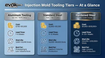
Tooling material selection matters:
| Tooling Material | Cost Range | Lead Time | Expected Life | Best Use Case |
|---|---|---|---|---|
| Aluminum (QC-10/7075) | $700–$10,000 | 1–6 weeks | 3,000–25,000 shots | Prototyping, low-volume production, design validation |
| Standard Steel (P20/718) | $2,800–$11,300 | 4–12 weeks | 50,000–100,000 shots | Medium-volume consumer products |
| Hardened Steel (H13/S136) | $11,000–$100,000+ | 8–20+ weeks | 500,000–1,000,000+ shots | High-volume production, abrasive materials |
Design changes after tooling is cut are where projects get expensive fast. Modifying steel costs far more than adjusting a CAD file—and some changes aren't feasible at all. Adding material to a mold cavity requires welding and re-machining, which can run nearly as much as cutting a new tool. Removing material is easier but still costly, and any modification resets your lead time clock.
Alternatives for low-volume or uncertain demand:
When design iteration risk is high or market demand is unproven, consider:
- Urethane casting: Cost-effective for 1 to 100 parts using 3D-printed master patterns, though silicone molds degrade after 20 to 50 shots
- Aluminum quick tooling: Produces 500 to 2,000 parts to validate market demand before investing in production steel molds
- FDM/SLA 3D printing: Best for functional prototypes and fit checks before any tooling spend — no minimum volumes, changes are free
Run your volume projections before committing to tooling, and build lead time into your schedule from day one. Producing fewer than 500 parts or still refining your design? Hold off on production tooling until the numbers and geometry are locked.
Design for Manufacturability Must Be Built In from the Start
The geometry decisions you make in CAD directly determine whether your part can be molded successfully. Get them wrong and you're looking at warping, sink marks, incomplete fill, or ejection damage. Design for Manufacturability principles need to be incorporated from the first sketch — not patched in after problems surface.
Wall Thickness: The Foundation of Everything
Uniform wall thickness is the single most important design rule in injection molding. When walls vary in thickness, different sections cool at different rates, creating internal stresses that cause warping, sink marks, voids, and incomplete fill.
Recommended wall thickness ranges by material:
| Material | Recommended Range |
|---|---|
| Polypropylene (PP) | 0.025"–0.150" |
| Nylon (PA6/66) | 0.030"–0.115" |
| Polycarbonate (PC) | 0.040"–0.150" |
| ABS | 0.045"–0.140" |
| PEEK (unfilled) | Minimum 0.040" |
Where thickness transitions are unavoidable, limit changes to 15% of nominal wall thickness and transition gradually over distance rather than creating abrupt steps.
Draft Angles: Non-Negotiable for Ejection
Draft is the slight taper applied to vertical walls that allows the cooled part to release from the mold without scraping or damage. Without adequate draft, parts grip the mold cavity during ejection, potentially damaging the part surface, bending ejector pins, or even cracking the mold.
Minimum draft requirements:
- Standard surfaces: 0.5° to 2° (general rule: 1° per inch of cavity depth)
- High-gloss optical surfaces: Add 1° to 3° beyond standard draft to overcome vacuum effects
- Textured surfaces: Add 1.5° per 0.001" of texture depth to account for micro-undercuts created by texturing
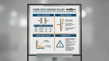
Radii and Fillets: Strength and Flow
Sharp internal corners create three problems: stress concentration points that weaken the part, flow restrictions that impede cavity fill, and mechanical interference that makes ejection difficult. Rounding corners solves all three.
General guidance:
- Internal radius: 0.5× wall thickness
- External radius: 1.5× wall thickness
This ratio improves part strength, promotes smooth resin flow, and reduces ejection force.
Undercuts: Expensive Complexity
Undercuts are features that prevent straight-pull ejection: internal recesses, external clips, or threads that require the mold to move laterally before the part can be removed. These features require side-actions, lifters, or collapsible cores that increase tooling costs by 15% to 30% and introduce long-term maintenance vulnerabilities.
Design alternatives to avoid undercuts:
- Convert internal features to pass-through holes
- Reposition the parting line to eliminate mechanical interference
- Use snap-fit designs that allow straight ejection
- Consider post-molding assembly for complex attachment features
Gate Location: Cosmetics and Structural Integrity
Gates are where molten resin enters the mold cavity. Their placement affects three critical outcomes:
- Gate vestige leaves a visible mark on the surface — placement determines whether it lands on a show surface or a hidden face
- Weld lines form where two flow fronts meet, creating a visible seam and a potential structural weak point
- Poor placement causes hesitation, air traps, or incomplete fill in deep or complex cavities
Identify cosmetically critical "show surfaces" early and communicate gate exclusion zones to your molder during design development, not after the mold is designed.
Material Selection Shapes Everything Downstream
Choosing your resin isn't just about mechanical properties or chemical resistance—it fundamentally determines what tolerances you can hold, how thick your walls can be, and whether your part will warp after ejection. Material selection must happen before you finalize geometry.
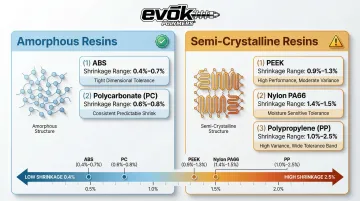
Amorphous vs. Semi-Crystalline: The Shrinkage Divide
Thermoplastics fall into two broad categories with very different molding behavior:
Amorphous resins (ABS, polycarbonate, polystyrene) have randomly organized molecular chains that solidify uniformly as they cool. This produces relatively isotropic shrinkage under 1%, making them dimensionally stable and easier to mold to tight tolerances.
Semi-crystalline resins (nylon, polypropylene, PEEK) develop organized crystal structures during cooling, resulting in higher shrinkage (often exceeding 1%) that varies based on fiber orientation and cooling rate. This anisotropic behavior makes them prone to warping, and dimensional control becomes significantly more process-dependent.
Shrinkage comparison:
| Resin Type | Material | Typical Shrinkage | Tolerance Capability |
|---|---|---|---|
| Amorphous | ABS | 0.4%–0.7% | Tight tolerances, excellent dimensional stability |
| Amorphous | Polycarbonate (PC) | 0.6%–0.8% | Good dimensional control, high impact resistance |
| Semi-Crystalline | PEEK (unfilled) | 0.9% (flow direction) to 1.3% (across flow) | Challenging tolerances, requires careful process control |
| Semi-Crystalline | Nylon (PA66) | 1.4%–1.5% | High shrinkage, moisture absorption affects dimensions |
| Semi-Crystalline | Polypropylene (PP) | 1.0%–2.5% | Highly variable shrinkage, excellent fatigue resistance |
Adding glass fibers to semi-crystalline resins reduces longitudinal shrinkage by 50% to 80% but increases anisotropy—the part shrinks differently in the flow direction versus perpendicular to flow, complicating dimensional control.
Geometry Constraints by Material
Each resin family imposes specific geometric limits. Locking in a material after geometry is finalized often forces costly redesigns. Key constraints to check early:
- Wall thickness: Amorphous resins can typically hold walls as thin as 0.030"–0.040"; semi-crystalline resins often require 0.060"+ for consistent fill
- Draft angles: Flexible resins like PP can release with as little as 0.5°; rigid or glass-filled materials typically need 1°–2° minimum
- Ribs and bosses: High-shrinkage resins exaggerate sink marks around thick features—rib thickness should stay at 50%–60% of nominal wall, not 75%
- Weld lines: Semi-crystalline resins form weaker weld lines than amorphous equivalents, which matters in high-stress or pressurized applications
Regulatory Requirements Lock In Material Choices
Geometry and shrinkage aside, regulated industries face a harder constraint: compliance standards eliminate most of the material shortlist before process optimization even begins.
- Medical devices (ISO 10993/USP Class VI): Require certified biocompatible grades that have passed cytotoxicity and systemic toxicity testing
- Food contact (FDA 21 CFR 177): Materials must comply with indirect food additive regulations
- Semiconductor (SEMI F57): Ultra-high purity components require extraction testing to ensure trace contamination stays in single-digit microgram ranges
Using unverified regrind or switching to a non-certified grade after production begins violates compliance and can require recertification—or complete material substitution and retooling.
Map your application environment—temperature exposure, chemical contact, regulatory compliance, UV exposure—before shortlisting materials. These constraints narrow your options quickly, and addressing them late means revisiting decisions you thought were already made.
Run Mold Flow Analysis Before You Cut Steel
Mold flow analysis is a computer simulation that models how molten resin fills the mold cavity, how the part cools, and where defects like air traps, weld lines, sink marks, and warping are likely to appear—all before any physical tooling is fabricated. For complex parts, it's among the highest-return steps an engineer can take before committing to steel.
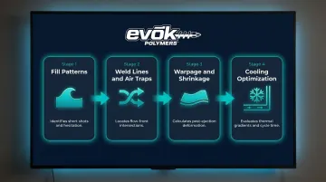
What Mold Flow Analysis Predicts
Modern simulation tools (Autodesk Moldflow, Moldex3D, SIMULIA) accurately predict:
- Fill patterns and short shots: Visualizes melt front progression to identify flow hesitation and incomplete filling
- Weld lines and air traps: Shows where flow fronts meet and where trapped air prevents complete fill
- Warpage and shrinkage: Calculates volumetric shrinkage and post-ejection deformation driven by uneven cooling
- Cooling optimization: Evaluates thermal gradients to improve conformal cooling channel placement and minimize cycle time
The ROI Case: Catching Problems in Simulation
Catching a defect in simulation costs a fraction of what it costs to rework steel. In one documented case, simulation reduced process development from 10-20 physical trial shots to just 1 virtual shot. Another study demonstrated a 25% reduction in raw material costs and 67% reduction in labor costs by optimizing runner designs virtually.
Beyond defect prevention, mold flow analysis informs:
- Gate location decisions that push weld lines to non-critical areas
- Runner system design to balance fill across multi-cavity molds
- Cooling channel placement to minimize cycle time and warpage
- Cycle time estimation for accurate production cost modeling
At EVOK, founder Paul Dathe treats mold flow studies as a standard step in new product development—not an optional add-on. It's how the team reduces tooling risk and builds accurate part pricing before a single dollar goes into steel.
When Simulation Is Essential vs. Optional
Mold flow analysis delivers the most value for:
- Complex geometries with thin walls, long flow paths, or multiple gates
- High-volume parts where tooling rework would delay production and impact revenue
- Cosmetic parts where weld lines, sink marks, or surface defects are unacceptable
- Fiber-reinforced materials where anisotropic shrinkage makes warpage difficult to predict manually
- Tight-tolerance assemblies where dimensional variation affects fit and function
For simple, thick-walled parts with loose tolerances and low production volumes, standard design rules may suffice without formal simulation.
Engage Your Manufacturer as a Design Partner—Not Just a Vendor
Waiting until your CAD is "done" to involve your injection molder is a strategic mistake. Any manufacturability issues discovered at that point require revisiting finalized geometry—potentially cascading into changes across your entire assembly. Early supplier involvement allows course corrections during design development, before anything is locked.
Why Early Involvement Matters
Injection molding is a manufacturing process with strict geometric requirements. Features that look perfectly reasonable in CAD—uniform wall thickness, adequate draft, avoidable undercuts—often aren't obvious to engineers without molding experience. Bringing your molder into the conversation during concept development means these issues get flagged and corrected while geometry is still fluid.
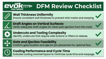
The DFM Review Process
A thorough Design for Manufacturability review examines your 3D model for:
- Wall thickness uniformity and transition quality
- Draft angles on all vertical surfaces
- Undercuts that drive tooling complexity and cost
- Gate and ejection feasibility based on part geometry
- Cooling performance and cycle time implications
Good manufacturing partners will flag cost drivers—like unnecessary undercuts or inconsistent wall thickness—and suggest design modifications that reduce tooling complexity without compromising fit or structural requirements.
At EVOK, pre-molding design reviews led by senior industrial designer Shawn Monitor have reduced project risk on large-scale programs by validating part features through prototyping and photorealistic rendering before any tooling investment is made.
Communicate Requirements Explicitly from the Start
A DFM review only works if your molder has the full picture. Your molder can't design tooling to meet requirements they don't know about—so communicate these upfront:
- Show surfaces: Identify cosmetically critical areas where gate vestige, ejector pin marks, or parting lines are unacceptable
- Surface finish requirements: Specify gloss levels, texture patterns, or SPI finish grades
- Gate exclusion zones: Mark areas where gates cannot be placed due to cosmetic or functional constraints
- Critical tolerances: Flag dimensions that affect fit, function, or assembly
Communicating these requirements upfront allows the molder to design tooling that respects them from the beginning, rather than discovering conflicts after the mold is fabricated.
Transparent Cost Structure Enables Better Decisions
Understanding what drives tooling cost—cavity complexity, number of actions, cooling channel design, surface finish requirements—allows you to make informed design trade-offs. For example, a single lifter action added to avoid a simple redesign can add thousands of dollars to tooling cost and slow cycle time.
EVOK is explicit about these cost drivers from the start, giving engineers the information they need to weigh design options before committing to tooling investment.
Frequently Asked Questions
What production volume justifies the investment in injection molding tooling?
Injection molding typically becomes cost-effective at volumes of several hundred to several thousand parts, depending on part complexity and tooling cost. For simple parts with modest tooling investment, breakeven can occur at 150-500 units, while complex geometries may require higher volumes to justify the upfront cost.
How do I know if my part design is ready to hand off for injection molding?
A design is ready when it incorporates DFM principles—adequate draft, uniform wall thickness, rounded corners, and no unintended undercuts—has been reviewed for material-specific requirements, and has ideally gone through mold flow simulation or a DFM review with your manufacturer.
What are the most common injection molding defects and how can they be prevented?
Common defects include sink marks, warping, short shots, weld lines, and flash—each tied to wall thickness, gate placement, venting, or clamp force issues. Most are preventable with proper DFM practices: uniform walls, adequate draft, strategic gating, and correct material selection.
What is the difference between aluminum and steel injection mold tooling?
Aluminum tooling is faster and cheaper to produce, making it suitable for prototyping and lower-volume runs (3,000-25,000 shots). Hardened steel costs more upfront but lasts far longer (500,000-1,000,000+ shots), making it the right call for high-volume production.
How long does it typically take to go from a finalized design to first production parts?
Aluminum tooling typically takes 1-6 weeks; hardened steel tooling takes 8-20+ weeks depending on complexity. Engaging your manufacturer early with a DFM-ready design is the most reliable way to avoid delays from tooling rework.