Introduction
Plastic parts that appear perfectly functional can silently deform over weeks, months, or years under sustained load. This phenomenon—called creep—is one of the most underestimated failure mechanisms in injection-molded components, and it can trigger costly field failures, recalls, or safety incidents. Honda recalled 340 motorcycles after radiant exhaust heat caused a plastic gear pedal pivot bolt seat to deform, reducing clamping force and eliminating gear shifting capability.
Creep is especially critical in load-bearing, high-temperature, or long-service-life applications—medical devices, powersports components, automotive assemblies, and semiconductor handling equipment. Creep resistance testing is the engineering discipline that quantifies and controls this risk before parts reach the field.
The challenge is that standard datasheet modulus values, which are derived from short-term tests, fail to predict real-world performance. In controlled testing, a constant 1-lb load on a polypropylene sample caused 60% more deflection in just four minutes than classical engineering formulas predicted. This article covers the testing methods, applicable standards, and best practices engineers use to close that gap.
Key Takeaways
- Creep is the slow, time-dependent deformation of a plastic part under constant stress—even at loads well below the material's yield point
- Key standards (ASTM D2990 and ISO 899-1) measure specimen deformation under sustained load at varied temperatures and stress levels
- Material choice, part geometry, and molding process parameters each affect real-world creep behavior
- Catching creep risk at the design stage costs far less than a failure discovered after tooling or in the field
What Is Creep in Plastic Parts?
Creep is time-dependent, permanent deformation that occurs when a plastic part is subjected to constant mechanical stress over an extended period, even when that stress is below the material's elastic limit. Unlike elastic deflection (immediate and recoverable), creep accumulates slowly and can become irreversible.
Creep vs. Stress Relaxation: A Critical Distinction
Creep and stress relaxation are often confused but represent distinct viscoelastic behaviors. Creep is measured as increasing strain under constant stress, while stress relaxation is the decrease in stress over time under constant strain. Both affect plastic parts but require different test setups and corrective design strategies.
For example, a snap-fit under constant deflection (strain) will experience stress relaxation, gradually losing retention force. A structural bracket under constant load (stress) will experience creep, gradually sagging.
The Three Stages of a Creep Curve
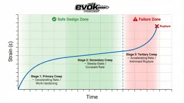
Polymer creep unfolds across three distinct stages:
- Primary (Transient) Creep : Characterized by an initial high creep rate that decreases with time as the material adjusts through elastic deformation, plastic deformation, and work hardening
- Secondary (Steady-State) Creep : The final stage where strain rate increases rapidly, leading to necking, cavitation, and imminent rupture
Most engineering design targets keeping parts within the primary or early secondary stage throughout their service life. Once tertiary creep begins, structural failure follows quickly — making early-stage creep data the foundation of any sound design specification.
Creep Testing Methods and Industry Standards
ASTM D2990 vs. ISO 899-1: When Each Applies
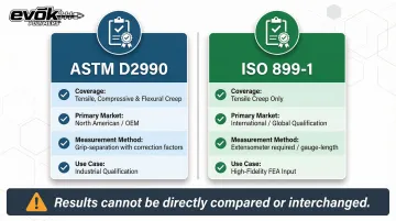
Two governing standards define creep testing for plastics, and their results cannot be directly compared or interchanged in simulation software:
ASTM D2990 (Standard Test Methods for Tensile, Compressive, and Flexural Creep and Creep-Rupture of Plastics) is widely used in North American industrial and OEM applications. It covers all three loading modes in a single standard and permits grip-separation measurements with correction factors.
ISO 899-1 (Plastics — Determination of Creep Behavior — Tensile Creep) is the international standard used for global product qualification. It strictly requires extensometers for engineering-grade gauge-length measurement, providing higher fidelity for FEA input by eliminating grip-slip errors.
Tensile Creep Testing
The most common method subjects a dogbone-style specimen to constant uniaxial tensile load at controlled temperature, tracking strain over time. This is most applicable to parts under sustained pulling or stretching loads, such as clips, retaining features, and snap-fit components common in injection-molded assemblies.
Compressive and Flexural Creep Testing
Compressive creep applies constant load in compression — relevant for gears, bushings, and structural supports that bear weight or resist crushing forces.
Flexural creep takes a different approach: the specimen bends under a sustained midpoint load, replicating how beams, brackets, and housings resist sagging under their own weight or attached components.
Matching the loading mode to the real-world application is critical—testing a bracket in tension when it experiences bending in service will produce misleading design data.
Short-Term vs. Long-Term Testing
The right test duration depends on what you need to know:
- Short-term tests (under one hour) characterize reversible viscoelastic behavior and are used for quick material screening — they show how a material responds immediately to load but cannot predict permanent deformation.
- Long-term tests (days, weeks, or months) capture irreversible deformation and are required for design validation in service-life applications.
Long-term tests typically use dead-weight loading frames rather than universal test machines (UTMs). A UTM tied up for a standard 1,000-hour test run costs far more than a passive dead-weight frame, making long-duration testing practical at scale.
Designing the Test Matrix
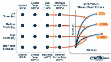
Experiments are typically structured across a matrix of stress levels and temperatures to capture creep behavior across the full service envelope:
- 3–4 stress levels spanning from low service stress up to near-yield
- 3–4 temperature points covering the expected operating range
- Fixed time points (commonly 100, 1,000, and 10,000 hours) for each condition
This data generates isochronous stress-strain curves — stress vs. strain at a fixed time point — that let engineers apply familiar stress-strain thinking to time-dependent behavior. Since each individual creep test yields only one point on an isochronous curve, multiple tests at varying stress levels are needed to construct a complete curve for interpolation.
How to Run a Creep Resistance Test: Step by Step
This section translates the standards into a practical testing workflow. The most common mistakes are under-specifying test conditions upfront, failing to control temperature precisely, and neglecting to log initial strain immediately after load application.
Step 1 – Define Test Objectives and Conditions
Specify the target stress levels based on anticipated service loads or a percentage of the material's tensile strength. Define the temperature range based on the end-use environment and the required test duration. Then establish your acceptance criteria before testing begins.
Key parameters to define upfront:
- Maximum allowable creep strain
- Whether creep rupture data is required
- Number of stress levels: ASTM D2990 requires at least 3 per temperature for linear viscoelastic materials, and at least 5 for non-linear (stress-sensitive) materials
Step 2 – Prepare Specimens
Prepare dogbone tensile specimens (or appropriate geometry for compressive/flexural testing) per ASTM D2990 or ISO 899-1 dimensions. For injection-molded parts, specimen orientation relative to flow direction is important because fiber-reinforced materials show anisotropic creep behavior. Specimens cut at 0° and 90° to flow direction can behave significantly differently, and both orientations should be tested where relevant.
Before loading, condition all specimens to moisture and temperature equilibrium. ASTM D618 requires 23°C (±2°C) and 50% (±10%) relative humidity for a minimum of 40 hours.
Step 3 – Set Up the Test Environment
Mount specimens in individual loading frames (for long-term tests) or a UTM (for short-term tests) equipped with a temperature-controlled environmental chamber. Set the temperature to the target value and allow the specimen to equilibrate before load application. Temperature stability throughout the test is critical because creep rate in plastics is highly sensitive to even small temperature fluctuations.
Extensometer selection directly affects data quality at elevated temperatures. Traditional clip-on contact extensometers introduce failure points in high-temperature chambers — they add physical drag to delicate specimens and are frequently destroyed during tertiary creep rupture. Non-contact video extensometers eliminate these risks by measuring strain through chamber windows using Digital Image Correlation (DIC), and can achieve Class 0.5 or Class B-1 accuracy under ISO 9513 and ASTM E83.
Step 4 – Apply Load and Begin Logging
Apply the target load smoothly to minimize dynamic impact on the specimen. Attach a calibrated extensometer to the gauge section to continuously measure strain. The extensometer range must capture both the large initial elastic strain and the smaller creeping strain that accumulates over long periods — at elevated temperatures, accuracy can degrade, which reinforces the case for non-contact measurement noted in Step 3.
Strain measurements must follow a logarithmic schedule to capture rapid primary creep and slow secondary creep: 1, 6, 12, and 30 minutes; followed by 1, 2, 5, 20, 50, 100, 200, 500, 700, and 1,000 hours.
Step 5 – Interpret Results and Apply to Design
Plot strain versus time on a creep curve and identify the three stages. Extract creep modulus (apparent modulus at a given time point), creep rate (slope of the secondary stage), and time-to-rupture if applicable. Isochronous stress-strain curves are the most useful design output because they allow engineers to use familiar stress-strain thinking for time-dependent material behavior.
For long-term predictions, the Time-Temperature Superposition Principle (TTSP) allows engineers to predict 10-to-20-year creep behavior using short-term (for example, 24-hour) tests conducted at elevated temperatures. Creep compliance curves collected at various temperatures are shifted horizontally along a logarithmic time axis to form a single "master curve" at a reference temperature.
Best Practices for Building Creep Resistance into Injection Molded Parts
Creep resistance is not just a material property—it is the result of material selection, part geometry, and process control working together. The most common engineering mistake is selecting a material with good short-term strength without evaluating its long-term creep data, especially at elevated temperatures.
Material Selection
Semi-crystalline polymers (e.g., POM, PEEK, nylon with moisture conditioning, PPS) generally outperform amorphous polymers in creep resistance due to their ordered molecular structure. These materials maintain their mechanical properties well past their glass transition temperature compared to amorphous polymers like polycarbonate or polysulfone.
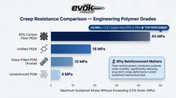
Fiber reinforcement significantly reduces creep rate by constraining polymer chain movement. Adding glass fiber or carbon fiber reduces the creep rate because rigid fibers constrain viscoelastic polymer chain mobility and bear a share of the applied load:
- Unfilled PEEK exhibits excellent creep resistance at room temperature but requires fiber reinforcement for structural applications at temperatures beyond its glass transition
- **40% carbon fiber PEEK** can sustain continuous stress of 45 MPa without exceeding 0.5% strain—2.5 times higher than PPS or PPA
- Glass-filled POM (Acetal) maintains flexural creep modulus after 1 year at 80°C higher than the initial modulus of unreinforced POM at 20°C
Always request and review long-term creep curves (not just tensile strength data sheets) when specifying materials for sustained-load applications. Relying on single-point modulus data alone leaves no margin for the time-dependent deformation that occurs under real service conditions.
Part Design Factors
Wall thickness uniformity, generous radii at stress concentrations, and proper rib/boss geometry all reduce localized stress that drives creep. Snap fits, press fits, and fastener bosses are particularly high-risk features because they impose sustained tensile or compressive stress on the plastic.
Snap-fit design considerations:
- Incorporate a fillet radius where the ratio of radius to wall thickness (R/t) is at least 50% to avoid stress concentration at the sharp corner between the beam and the wall
- Use a 90° return angle so the joint relaxes in tension rather than bending, preventing stress relaxation from reducing holding force
Boss and rib guidelines:
- The outside diameter of a fastener boss should be 2 to 3 times the hole diameter to withstand molded-in hoop stress
- Ribs should be 50% to 67% as thick as the walls they reinforce to prevent differential shrinkage and sink marks
These features should be analyzed against creep data and, where possible, validated with physical creep tests before committing to tooling. Evok Polymers' pre-molding design review process specifically addresses these risk factors to reduce the chance of discovering creep issues after the tool is cut. Getting process parameters right from the start matters just as much—how a part is molded directly shapes how fibers orient and where vulnerabilities form.
Process and Orientation Considerations
Injection molding process parameters directly affect creep behavior in fiber-reinforced materials. Flow direction governs fiber orientation, and weld lines—where two flow fronts meet—create zones of reduced fiber reinforcement that are more susceptible to creep.
Fiber orientation varies by layer: Injection-molded parts develop a "skin-core-skin" structure where fibers in the shell align parallel to the flow direction (0°), while fibers in the core align transverse to the flow (90°). As a result, fiber-reinforced composites are highly creep-resistant in the flow direction but significantly weaker in the transverse direction.
Weld lines revert to unreinforced matrix properties: At weld lines, the interface is resin-rich because fibers do not cross the boundary. This lack of fiber bridging reduces the local area to the brittle, low-strength behavior of the unreinforced matrix. In PA6 reinforced with 30% fiberglass, weld lines show severely reduced elongation (4.30% to 4.80%). Placing a weld line in a high-stress area makes localized creep rupture highly probable.
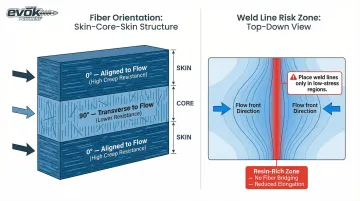
Mold flow analysis, run before tooling begins, predicts both fiber orientation and weld line locations. This lets designers reposition gates and adjust flow paths so that weld lines form only in low-stress regions—before a single dollar is spent on tooling steel.
How EVOK Polymers Can Help
EVOK Polymers works with OEM customers from material selection and DFM through production, so creep performance is treated as a design variable from the start rather than addressed after problems surface. With 25 years of injection molding expertise, EVOK applies hands-on knowledge of polymer behavior, mold flow analysis, and tolerance analysis to help customers design parts that meet long-term performance requirements.
Pre-tooling design reviews catch creep vulnerabilities before a single dollar is spent on tooling. Each review covers:
- Load-bearing feature geometry and stress concentration points
- Wall thickness consistency and its effect on long-term deformation
- Fiber orientation strategy for reinforced materials
- Weld line locations and their creep vulnerability under sustained load
Catching these issues early costs far less than a post-launch field failure. Customers across powersports, semiconductor handling, and medical device manufacturing have used this process to avoid costly recalls and warranty claims.
Conclusion
Creep in plastic parts is a slow, cumulative failure mechanism that standard short-term mechanical testing will not reveal. Creep resistance testing using ASTM D2990 or ISO 899-1, designed across the right range of stress levels and temperatures, is how OEMs validate long-term part performance before parts reach the field.
Creep resistance requires attention at three connected levels:
- Material selection — choose resins with long-term creep data at your actual service stress and temperature
- Part geometry — design to minimize sustained stress concentrations at bosses, snap fits, and load-bearing walls
- Process control — manage fiber orientation and weld line placement to avoid hidden weak zones
Addressing all three during design validation costs a fraction of what a field failure investigation demands. The earlier creep behavior enters the engineering conversation, the fewer surprises make it to production.
Frequently Asked Questions
What is the difference between creep and stress relaxation in plastics?
Creep is increasing strain under constant stress over time, while stress relaxation is decreasing stress under constant strain over time. Both arise from the viscoelastic nature of polymers but require different tests and have different design implications—creep affects load-bearing components, while stress relaxation affects retention features like snap-fits.
Which plastics have the best creep resistance?
Semi-crystalline polymers such as PEEK, PPS, and POM generally offer superior creep resistance compared to amorphous polymers, and glass or carbon fiber reinforcement further reduces creep rate. Material choice should always be validated against long-term creep curves at the actual service temperature, not just datasheet modulus values.
What are the main standards for creep testing of plastic parts?
ASTM D2990 covers tensile, compressive, and flexural creep and creep-rupture, while ISO 899-1 addresses tensile creep for international qualification. The applicable standard depends on the customer's market, application requirements, and whether North American or international qualification is needed—their results cannot be directly compared.
How long does a creep test for plastic parts typically take?
Short-term creep tests run under one hour and are used for material screening to capture reversible deformation behavior. Long-term tests designed to capture irreversible deformation for design validation may run for days, weeks, or months depending on required service life and stress levels—standard tests often run 1,000 hours.
How does temperature affect creep in injection-molded plastic parts?
Elevated temperature accelerates creep rate in plastics because heat increases polymer chain mobility. Even moderate temperature increases above ambient can substantially increase creep deformation, making it essential to test at or above the maximum expected service temperature—a material that performs well at 23°C may fail rapidly at 60°C.
Can creep in plastic parts be fully prevented?
Creep will always occur in polymers to some degree, but proper material selection, part design that minimizes sustained stress concentrations, and process controls that optimize fiber orientation keep it within acceptable limits. The engineering goal is to ensure creep strain stays within allowable bounds throughout the part's service life.