Have you ever assembled plastic parts only to find they don’t fit, snap, seal, or align the way the design intended?
Many product failures begin with tolerance assumptions that work on CAD but fail in molded reality.
Studies show that poor quality and rework can cost manufacturers 5% to 35% of total production expenses, often driven by dimensional variation and assembly mismatch.
The problem is not just measurement; it is prediction. Plastic shrinks, flows, and cools differently than metal. Without planning for that behavior, parts warp, shift, or stack outside allowable limits. Engineers solve this using material-aware design, controlled processing, and validation before full production.
In this guide, you will learn what plastic injection molding tolerances mean, how design and processing influence them, and how to validate tolerances before committing to tooling.
Key Takeaways
Tolerance starts with material physics, not CAD intent. Shrinkage behavior sets limits before tooling decisions ever matter.
Geometry controls stability more than machine precision. Uniform walls and balanced flow reduce dimensional drift significantly.
Tool design defines repeatability, processing defines consistency. You need both aligned to achieve reliable production dimensions.
Tighter tolerances increase cost exponentially, not gradually. Specify precision only where the function truly demands it.
Early validation prevents late-stage engineering compromises. Prototype measurement protects schedule, tooling, and assembly performance.
What Plastic Injection Molding Tolerances Mean in Manufacturing?
Plastic injection molding tolerances define how much a molded dimension may vary while remaining acceptable. Unlike machining, molded parts naturally change shape during cooling and shrinkage.
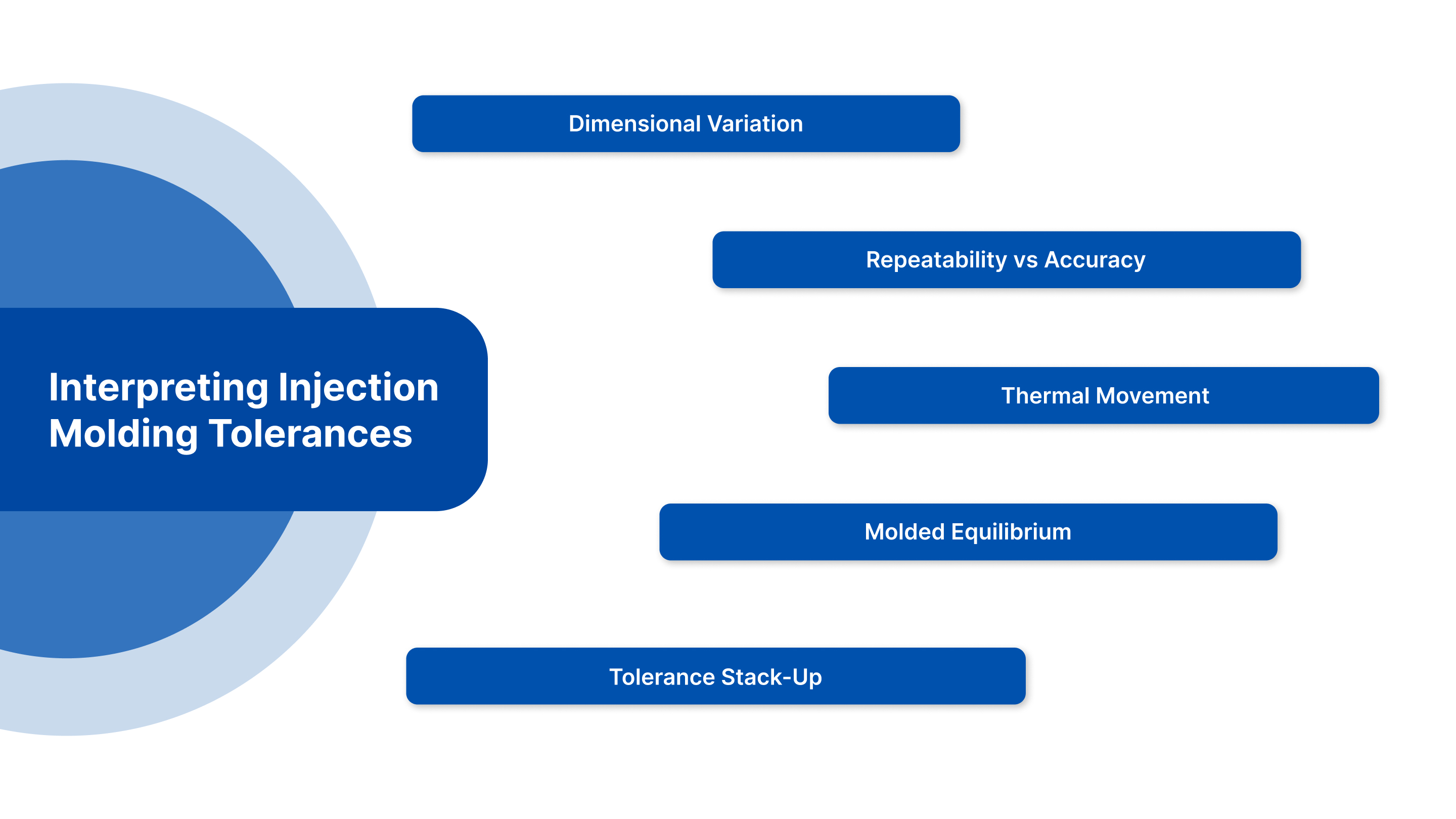
Key concepts:
Dimensional variation: Parts rarely match CAD perfectly because molten plastic contracts as it cools inside the mold. Flow direction, wall thickness, and cooling rate create uneven shrinkage that shifts final dimensions from nominal values.
Repeatability vs accuracy: A molding process can repeatedly produce identical parts that are consistently offset from the target dimension. Accuracy means hitting nominal size, while repeatability means producing the same result every cycle.
Thermal movement: Plastics expand and contract far more than metals when temperature changes. Post-molding cooling, ambient storage conditions, and operating temperature all influence final measurements and functional fit.
Molded equilibrium: Some materials continue stabilizing after ejection as internal stresses relax, and temperature equalizes. Dimensions measured immediately after molding may differ from measurements taken several hours or even days later.
Tolerance stack-up: When multiple molded components assemble, small dimensional variations accumulate. Even if each part meets its tolerance individually, combined variation can cause gaps, interference, leakage, or misalignment in the final assembly.
Understanding these fundamentals sets realistic expectations before specifying tight limits.
Industry Tolerance Standards and Classes Used in Plastic Parts
Manufacturers categorize tolerances into practical classes so designers avoid unrealistic requirements.
Common classifications:
Commercial tolerance: Applied to non-critical consumer parts such as covers and housings. Minor dimensional variation is acceptable because the function does not depend on a precise fit. This keeps tooling simple, improves yield, and lowers manufacturing cost.
Medium precision: Used for parts that must assemble reliably, such as brackets, clips, and snap features. Dimensions are controlled more tightly than cosmetic parts, ensuring repeatable alignment while still allowing normal molding variation without expensive secondary operations.
Tight tolerance: Required when sealing surfaces, gear engagement, or guided movement is involved. Small dimensional shifts can affect performance, so tooling, material selection, and process control must be carefully optimized to maintain consistency.
Micro precision: Applied to miniature or high-accuracy components like medical or micro-mechanical parts. Achieving this level often requires high-precision molds, controlled environments, detailed inspection methods, and sometimes post-machining or calibration steps.
Material-dependent adjustments: Different plastics shrink and flex differently. Filled resins, such as glass-filled nylon, hold dimensions better, while flexible materials vary more. Tolerances must therefore be widened or tightened depending on the polymer’s stability.
Standards prevent over-engineering and reduce unnecessary tooling complexity.
Why Plastic Injection Molding Tolerances Matter for Fit, Function, and Assembly Performance?
Tolerance decisions determine whether parts assemble easily or fail repeatedly.
Functional impact includes:
Snap-fit engagement: If tolerances are tighter than material flexibility allows, the joint overstresses and cracks during assembly. In case it’s too loose, the retention force drops and parts disengage during vibration, handling, or long-term product use.
Sealing performance: Gaskets and sealing lips require controlled compression. Excess dimensional variation prevents uniform contact pressure, creating leak paths for air or liquid and causing inconsistent waterproofing across production batches.
Bearing alignment: Rotating shafts depend on coaxial alignment. Small positional errors shift load distribution, increasing friction, heat generation, premature wear, and audible noise during operation, especially in motorized or gear-driven assemblies.
Electrical contact reliability: Plastic housings position metal terminals. Incorrect tolerances reduce terminal compression force, raising electrical resistance, intermittent connections, overheating, or signal instability in connectors, switches, and electronic modules.
Stack-up accumulation: Multiple acceptable variations combine across assemblies. Individually compliant parts can collectively exceed functional limits, leading to misalignment, cosmetic gaps, fastening difficulty, or complete assembly failure during production.
Material Behavior and Shrinkage Effects on Plastic Injection Molding Tolerances
Each resin behaves differently during cooling and crystallization.
Critical influences are as follows:
Shrink rate variability: Semi-crystalline plastics continue reorganizing their molecular structure after molding, causing higher and less predictable shrinkage than amorphous plastics. This makes tight tolerances difficult without compensation factors built into the mold dimensions.
Glass fiber orientation: Reinforced plastics shrink unevenly because fibers restrict movement along the flow direction but not across it. This anisotropic behavior causes warpage, oval holes, and dimensional drift unless gating and flow paths are carefully planned.
Moisture absorption: Hygroscopic resins such as nylon absorb atmospheric moisture after molding, gradually expanding dimensions. Parts that pass inspection initially may move outside tolerance later if conditioning, packaging, or environmental exposure is ignored.
Thermal contraction: Thicker sections retain heat longer, cooling at different rates than thin walls. Uneven contraction pulls the part out of shape, shifting critical dimensions and creating flatness or alignment problems across mating components.
Fillers and additives: Mineral fillers, glass beads, and stabilizers reduce molecular movement during cooling. They improve dimensional stability and repeatability but may increase brittleness, requiring design adjustments to balance tolerance and mechanical performance.
Material selection often determines achievable tolerance before mold design begins. Geometry must now support that behavior.
Part Geometry Design Rules That Control Achievable Tolerances
Shape affects dimensional stability more than most engineers expect, which is why smart geometry decisions directly improve dimensional control before process adjustments even begin.
Design rules that strengthen tolerance capability:
Uniform wall thickness: Consistent wall thickness allows the part to cool evenly throughout the mold cavity. When thickness varies, sections shrink at different rates, causing warpage, internal stress, and dimensional shift away from critical tolerance targets.
Balanced ribs: Properly proportioned ribs increase stiffness without creating sink marks or differential shrinkage. When rib thickness stays within recommended ratios, the part maintains structural support while preserving surface quality and dimensional accuracy.
Proper draft angles: Adequate draft reduces friction during ejection, preventing deformation or drag marks. Insufficient draft forces the part against the mold steel, distorting walls and altering critical dimensions immediately after release.
Rounded transitions: Sharp internal corners concentrate stress and restrict material flow, increasing shrink variation. Smooth radii promote consistent filling and cooling, reducing internal stress buildup that can shift final dimensions.
Flatness support features: Large flat surfaces tend to warp during cooling. Adding gussets, ribs, or structural contours distributes shrink forces evenly, improving flatness and preventing post-mold dimensional distortion.
Good geometry minimizes variation at the source, and tooling influence must not be overlooked.
Tooling and Mold Design Factors That Influence Tolerance Capability
Once part geometry is stable, dimensional repeatability depends on how accurately the mold controls material flow, cooling, and mechanical stability during every cycle.
Key mold design elements that govern tolerance consistency:
Core and cavity alignment: Accurate alignment prevents parting line mismatch and flashing. Even a slight offset causes uneven wall thickness and dimensional shift, especially in precision fits, making repeatable assembly difficult across production batches.
Cooling channel placement: Strategically placed cooling lines maintain uniform temperature across the cavity. Uneven cooling produces differential shrinkage, which leads to warpage, ovality, and gradual dimensional drift between early and late production cycles.
Gate location: Gate position determines how the packing pressure distributes inside the cavity. Poor placement creates over-packed and under-packed zones, resulting in inconsistent dimensions, sink marks, and unpredictable tolerance variation across the part.
Venting strategy: Proper venting allows trapped air to escape during filling. Without it, gas compression causes burns, short shots, and localized dimensional inaccuracies that prevent consistent tolerance achievement.
Steel rigidity: Mold steel must resist deflection under clamp force and injection pressure. Flexible tooling slightly expands each cycle, producing dimensional variation even when machine settings remain constant.
A precise tool still requires stable processing to hold dimensions.
Processing Parameters That Affect Dimensional Stability
Machine settings control the final molded dimensions cycle after cycle.
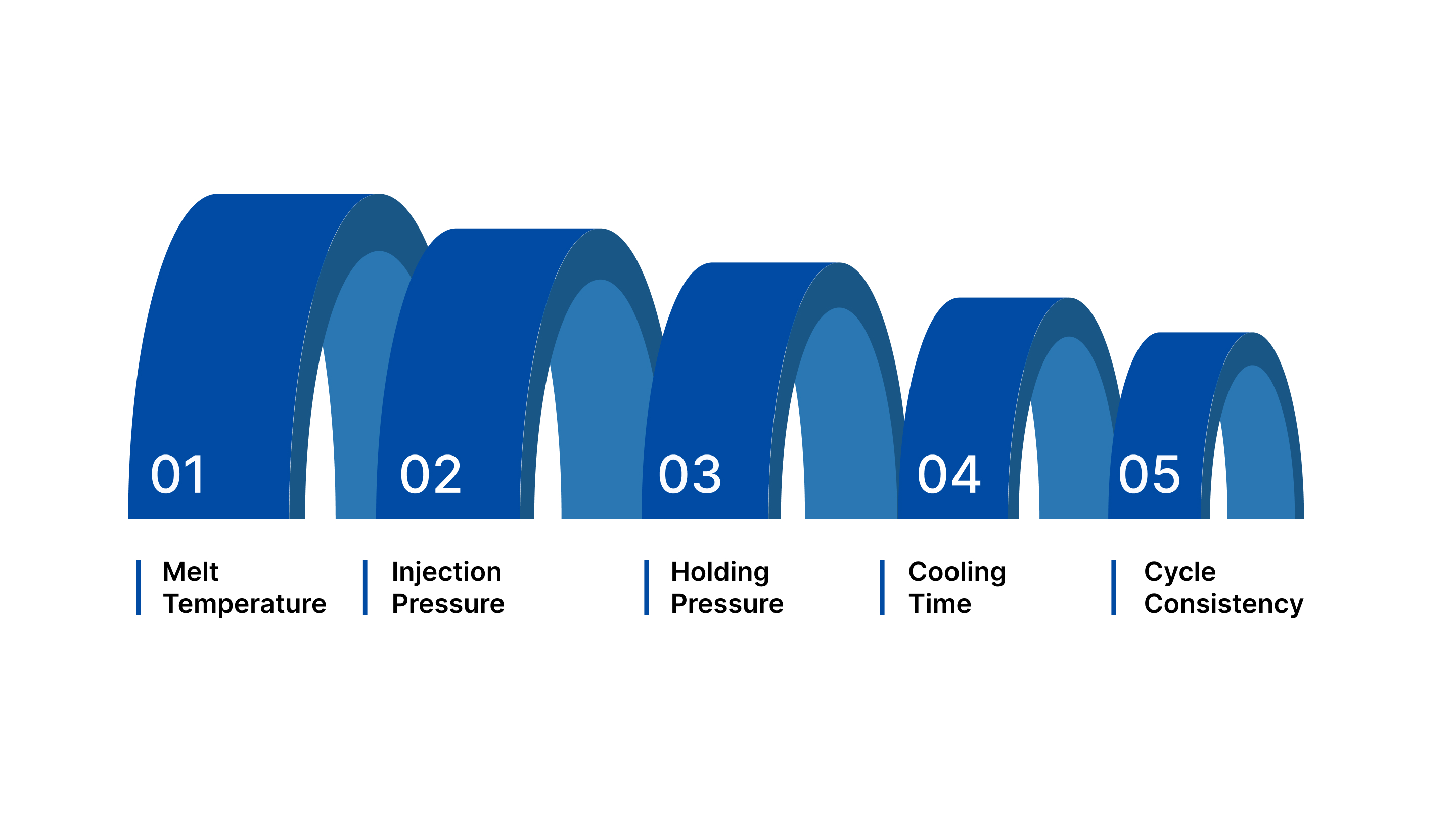
The following processing conditions directly influence part accuracy and repeatability:
Melt temperature: Alters polymer viscosity and flow behaviour. If too high, the material over-packs and shrinks more after cooling; if too low, incomplete filling and higher internal stress lead to dimensional variation.
Injection pressure: Determines how completely the cavity fills. Insufficient pressure causes short shots and inconsistent wall thickness, while excessive pressure over-packs material, increasing post-mold shrinkage and warpage risk.
Holding pressure: Maintains material packing as the gate freezes. Proper holding compensates for cooling contraction; too little creates sink marks and undersized parts, too much locks internal stress that distorts dimensions later.
Cooling time: Controls solidification uniformity through the wall section. Short cooling traps heat and leads to deformation after ejection, while optimized cooling stabilizes molecular structure and maintains dimensional consistency.
Cycle consistency: Variations in cycle time, delay, or temperature gradually shift part dimensions. Even small fluctuations accumulate over production runs, producing dimensional drift despite identical machine settings.
Even with stable processing, measurement confirms capability.
Measurement Methods and Inspection Techniques for Molded Parts
Validation ensures tolerances are real, not theoretical.
The following inspection approaches verify dimensional performance and reveal hidden variation before production scale-up:
CMM measurement: A coordinate measuring machine maps critical dimensions using probing points across features. It delivers micron-level accuracy, identifies geometric deviation patterns, and confirms whether molded parts consistently meet engineering tolerances.
Optical scanning: Structured-light or laser scanners capture full-surface geometry quickly. Engineers compare scans against CAD models to visualize warpage, shrink variation, and cosmetic distortion without touching soft plastic surfaces.
Gauge R&R studies: Measurement system analysis evaluates repeatability and reproducibility across operators and equipment. It confirms whether observed variation comes from the molding process or unreliable measurement methods.
Capability studies (Cp/Cpk): Statistical evaluation measures how well production stays within tolerance limits. A capable process demonstrates predictable output and indicates whether design or process adjustments are required.
Sampling plans: Defined inspection frequency monitors dimensional drift during production. Early detection prevents large batches of nonconforming parts and supports corrective action before shipment or assembly issues occur.
Results guide design adjustments before full production investment.
Design for Manufacturing (DFM) Strategies to Achieve Tight Tolerances
Engineers refine designs instead of forcing unrealistic limits. Instead of tightening every dimension, smart DFM focuses on precision where it truly affects performance while reducing unnecessary manufacturing strain.
The following DFM strategies help balance precision, cost, and repeatability:
Relax non-functional dimensions: Not every feature requires a tight tolerance. Over-specifying cosmetic or clearance features increases tooling complexity and scrap rates. Identify functional dimensions tied to fit, sealing, or motion, and widen limits on non-critical areas to stabilize production and reduce inspection burden.
Add alignment features: Stack-up errors occur when multiple parts depend solely on dimensional accuracy. Incorporate locating pins, bosses, datum surfaces, or self-aligning geometry so assembly accuracy depends less on cumulative tolerances and more on controlled reference points.
Select stable materials: Material choice influences achievable tolerance before tooling begins. Choose resins with low shrink variation, minimal moisture absorption, and predictable thermal behavior. Reinforced or filled grades often improve dimensional repeatability in tight-fit applications.
Use secondary machining selectively: When ultra-tight precision is unavoidable, machine only the critical feature after molding. This hybrid approach maintains molding efficiency while achieving the required accuracy without redesigning the entire part or overcomplicating the mold.
Validate prototypes first: Prototype tooling or pilot runs reveal real-world shrinkage and distortion. Testing early allows dimensional adjustments before hard steel tooling is finalized, preventing expensive rework and delayed product launches.
However, even strong DFM planning must account for common molding risks that can still affect tolerance control.
Common Tolerance Problems and How Engineers Fix Them
Even well-designed parts can drift outside tolerance if shrinkage, pressure distribution, or tooling balance is not controlled. Identifying the root cause early prevents repeated dimensional failures during production.
Typical molding issues and solutions:
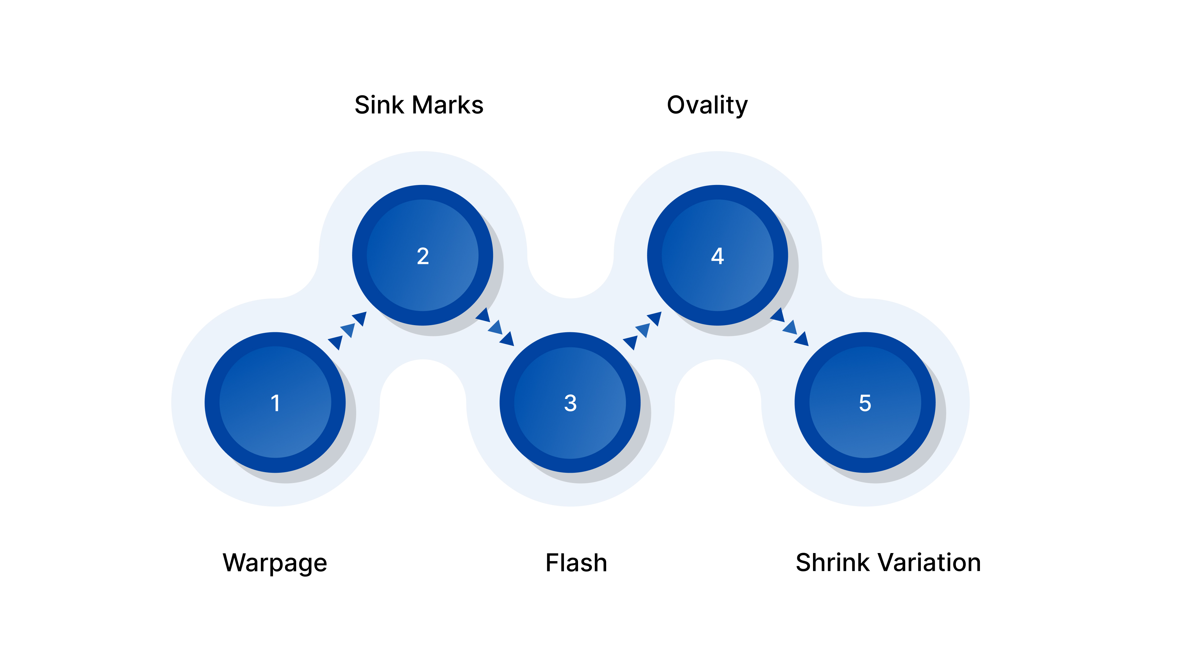
Warpage: Warpage occurs when different areas of the part cool and shrink unevenly, pulling the geometry out of shape. This often results from inconsistent wall thickness or poor cooling layout.
Balance cooling channels, maintain uniform wall sections, and optimize packing pressure to equalize shrinkage across the part.
Sink Marks: Sink marks appear as surface depressions caused by internal shrinkage in thicker areas, especially near ribs or bosses. They indicate insufficient packing or improper rib design.
Increase holding pressure and time, reduce rib thickness to recommended ratios, and adjust gate placement to improve material packing.
Flash: Flash forms when molten plastic escapes between mold parting surfaces, creating thin, unwanted material edges. It often results from mold misalignment, excessive pressure, or worn shutoffs.
Increase clamp force, reduce injection pressure if excessive, and repair or improve shutoff surfaces for tighter sealing.
Ovality: Ovality occurs when round features, such as holes or cylinders, shrink unevenly due to fiber orientation or uneven packing. This affects bearing fits and alignment accuracy.
Adjust gate location to balance flow, optimize cooling symmetry, and modify material selection if fiber-induced distortion persists.
Shrink Variation: Shrink variation causes inconsistent dimensions between production runs or across cavities. It often results from unstable temperature, moisture variation, or inconsistent packing.
Stabilize material drying, control melt and mold temperatures, and define a consistent process window validated through capability studies.
Preventing these problems requires early collaboration before steel is cut.
How Evok Polymers Can Help Validate Plastic Injection Molding Tolerances Before Production?
Evok Polymers works with OEMs and product developers to confirm tolerances before committing to production tooling.
We help by:
Performing DFM reviews: Analyze drawings and GD&T to flag unrealistic tolerance zones, stack-up risks, and shrink-sensitive features before tool steel is ordered, reducing redesign cycles.
Running mold flow simulations: Predict shrinkage patterns, fiber orientation, and warpage so engineers can adjust geometry, gates, and cooling layout prior to manufacturing.
Selecting materials: Recommend resins based on shrink rate stability, moisture sensitivity, and thermal behavior aligned with dimensional requirements rather than only mechanical properties.
Building prototype tooling: Produce bridge or soft-tool samples to measure actual molded dimensions and verify tolerance capability under production-like conditions.
Establishing process windows: Define stable melt temperature, pressure, and cooling ranges using capability studies so production consistently holds dimensions over long runs.
Early validation prevents expensive redesign later.
Conclusion
Plastic injection molding tolerances determine whether parts assemble smoothly or create ongoing production problems.
Many failures occur because designs assume machining-level precision without accounting for shrinkage, material behavior, and processing variation.
The most successful projects combine realistic tolerance planning, simulation, and early testing before full tooling investment.
Are you trying to meet tight dimensional requirements but unsure if molding can reliably achieve them?
Evok Polymers helps engineers evaluate tolerance feasibility, validate dimensions, and stabilize production before launch. Request a quote to understand achievable tolerances, tooling strategy, and production readiness for your next molded component.
Frequently Asked Questions
1. What tolerance can injection molding typically achieve?
Typical plastic injection molding tolerances range from ±0.005 to ±0.020 inches, depending on material, geometry, and size. Engineering resins and smaller parts hold tighter limits, while flexible plastics require looser ranges. Achievable tolerance always depends on shrink rate, cooling uniformity, and tool precision rather than machine accuracy alone.
2. Why are plastic tolerances looser than metal machining?
Plastics shrink and deform during cooling, while metals are cut from solid stock. Thermal expansion, molecular orientation, and moisture absorption cause dimensional variation. Injection molding is a forming process, not a removal process, so tolerances must accommodate material behavior instead of forcing fixed dimensions like machining.
3. How does material choice affect molding tolerance capability?
Amorphous plastics like ABS or polycarbonate hold tighter tolerances because they shrink uniformly. Semi-crystalline plastics like nylon or polypropylene shrink more and vary with flow direction. Glass-filled materials improve stability but introduce directional variation, so designers must orient critical dimensions carefully.
4. Can tight tolerances be improved after tooling is built?
Yes, but only within limits. Process optimization, gate adjustments, and controlled cooling can improve consistency. However, major dimensional corrections usually require tool steel modification, which increases cost and delays. That’s why tolerance validation during design and prototyping is essential.
5. How do engineers verify tolerance capability before production?
Engineers use prototype tooling, capability studies (Cp/Cpk), and CMM measurements to compare molded parts against drawings. Mold flow simulation predicts variation before cutting steel, and pilot production runs confirm repeatability. This validation ensures parts assemble correctly before full-scale manufacturing begins.