LIFE OF THE PART:
Let’s take a trip into the future to see just what we are expecting from our part! its so important to visualize how your part will be used in the field under the worse situations possible. Is it intended to fail at a certain cycle, impact, rotation, stress? How does cold or hot environments affect these changes? How about moisture, or prolonged UV exposure? Some polymers have excellent resilience to temperature fluctuation whereas others fail miserably under certain interactive instances. Let us put on the white gloves to help you understand exactly what your suitable material choice will be and how we can maximize your geometry to absorb both physical and environmental elements and give you a predictable expectation of life for your product!

Plastic part defects can be traced to 1 of 3 sources:
- Resign or Additive
- Injection Molding Process
- The Mold and Mold Design
3. BURN MARKS:
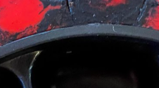
Generally, Burn marks are born on the surface of the part and can usually be found the opposite of the gate location. This is due to a gas trap at the end of the filling cycle where the gas ignites and burns the part at the end of fill. The second area of burn can occur at the gate where the plastic flows into the part. this is usually the tightest orifice of the filling process which in turn adds heat due to material sheer rates. PVC is an example of a sheer sensitive material where burning can occur at the gate
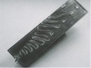
4. FLOW MARKS:
Lined patterns that are often wavy or show discoloration on the surface of the part. most commonly caused by resign that is cooling too quickly. In some cases, flow marks can be eliminated by increasing injection speed and pressure to increase uniformity of filling and cooling. Sometimes a gate location change is needed.
5. FLASH:
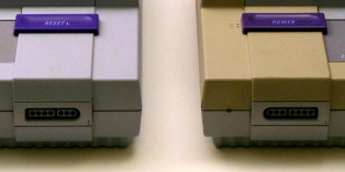
One of the most pronounced common visual defects of an injection molded part where small waferlike protrusion the wraps along the parting line or ejector pin locations due to escaping the mold cavity. Flash can be caused by too high of a mold temperature, not enough clamping force in relation to melt flow, or excessive barrel heat.

6. KNIT LINE:
Weak knit lines- Also called “Weld Lines” are where 2 flow fronts of material come together around a geometric detail in a part such as a boss. Knit lines are apparent in every part and when defective will almost always be the weakest area of a part. In extreame cases weak knit lines and can result in cracks. Cause of knitlines can also appear when material is not processed hot enough. or when circling a cold insert such as a threaded insert
8. SPLAY:
Witnessed by space-like streaks inline with the flow lines. It is a surface defect that occurs by gas bubbles that are dragged across the surface of the part. Splay is usually caused by moisture trapped within a moisture-sensitive material that has not been adequately dried. Splay can also result from a leaky cooling line within a mold.
9. JETTING:
Jetting is usually seen as a wavy worm-like visual defect on a surface where molten plastic solidifies early and is then pushed to the surface as the cavity fills. Jetting can usually be eliminated with process control changes.
MOLDING TRIAL REPORT
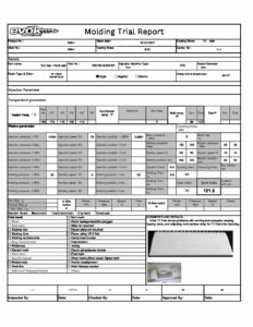
Molding Trial report is one of the most important steps in the qualification of your part. Keep in mind all these factors play into getting you to the perfect part for your application. T1 Samples will be evaluated prior to Texturing and will show 90% of how the part will mold. At this time adjustments are commonly made to the mold and process including but not limited to Gate sizing, Vent sizing, and location, wall thickness modification to minimize sink and match plating to minimize any flash.
At this time Process parameters are also monitored very closely to understand how fast the mold fills, where any knit lines end up with respect to the original mold flow analysis. Zone temperatures, and of course cycle time are needed to complete the process for an acceptable part and its impact on the financial metrics.
Rely on us to find the right tool to solve your analytical problem. Those motivated and Skilled in the art of problem solving will give you confidence.
GET STARTED
Reach out to us and get full access to our Polyestimator!

